
Controller of vehicle

Inactive Publication Date: 2005-10-04
AISIN AW CO LTD
View PDF12 Cites 24 Cited by
  • Summary
  • Abstract
  • Description
  • Claims
  • Application Information

AI Technical Summary

Benefits of technology

[0012]Further, the ignition condition setting means may lowly set the ignition starting rotation number when the load torque given to the motor on the basis of a large load condition and highly set the ignition starting rotation number when the load torque given to the motor on the basis of a small load condition.
[0032]The embodiment can also be such that the ignition condition correcting means corrects the ignition condition on the basis of the temperature of the battery as the predetermined condition. Accordingly, the ignition timing of the engine can be changed in accordance with the temperature of the battery. Thus, for example, when the temperature of the battery is low, the ignition timing of the engine is hastened so that electric power consumption is restrained. Thus, a voltage drop can be prevented. Additionally, the temperature of the battery can be detected by detecting the external air temperature of the vehicle.

Problems solved by technology

When the engine is ignited, or initially started, in the state of low speed rotation, a relatively large torque is required to start the rotation of the engine.
Accordingly, a large amount of fuel is used so that the amount of discharge gas is increased and has a bad influence on, e.g., an exhaust device, such as a muffler.
Accordingly, there is a fear that the so-called emissions become worse.
However, for example, when the engine has a low temperature (namely, the water temperature of the engine is low) and an automatic speed change gear has a low temperature (namely, the temperature of lubricating oil is low and the viscosity of the lubricating oil is high), etc., their dragging torques are large.
Accordingly, when the engine and the automatic speed change gear are rotated by the motor in advancing the vehicle, a relatively large amount of electric power is consumed.

Method used


Image

  • Controller of vehicle
  • Controller of vehicle
  • Controller of vehicle

Examples


Embodiment Construction

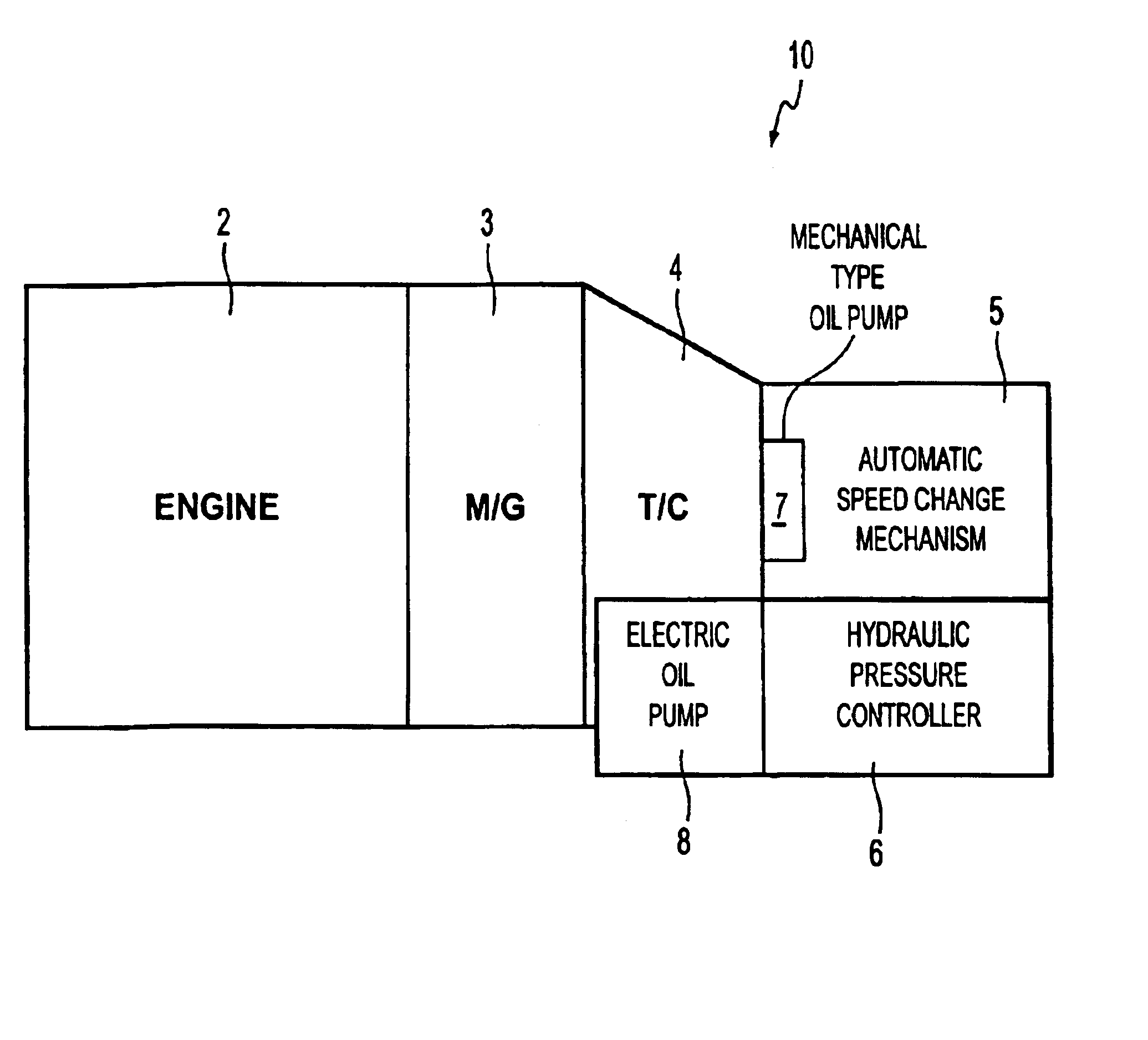
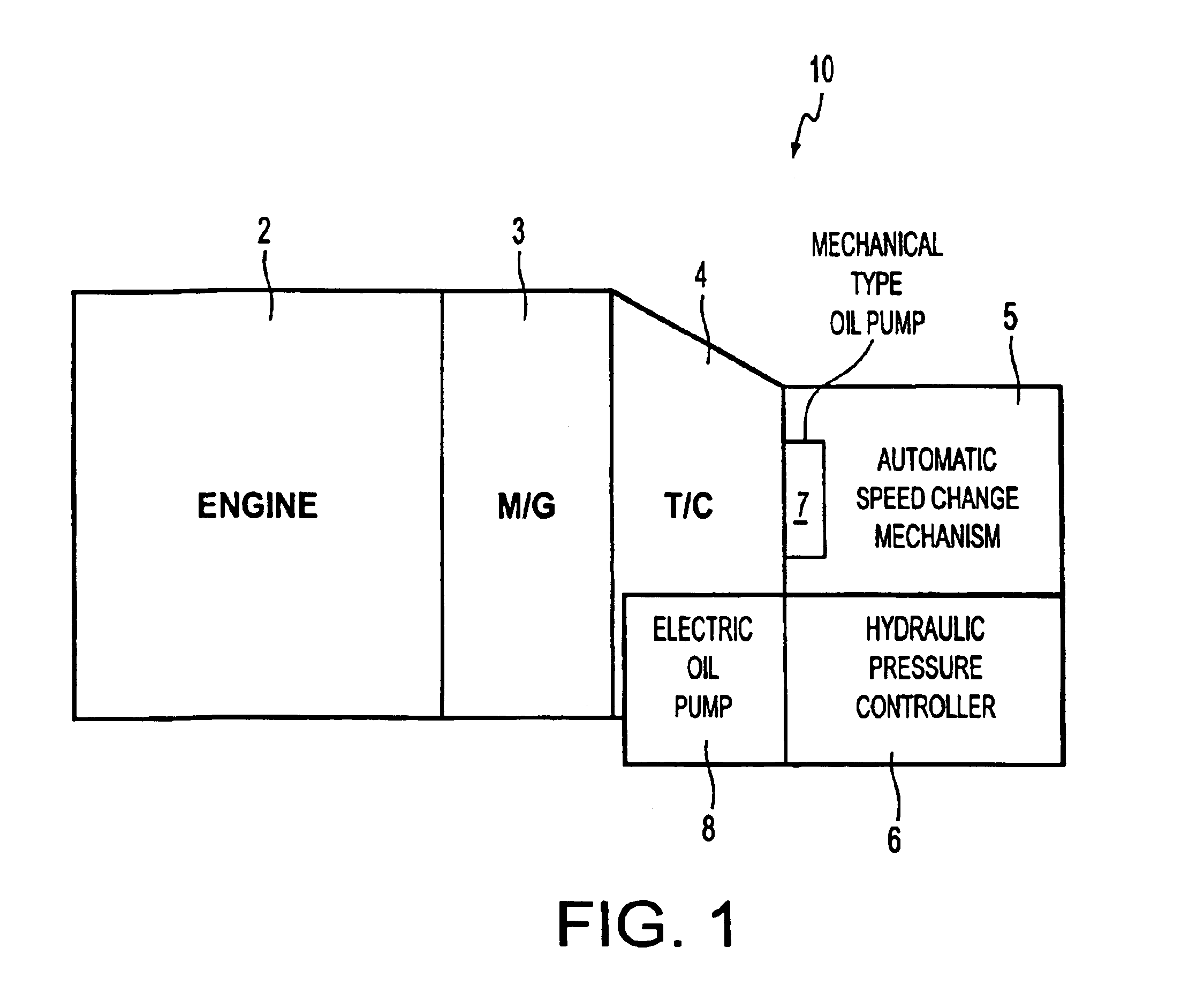
[0041]The driving system of a vehicle able to apply the vehicle controller of the invention thereto will first be explained using FIG. 1. As shown in FIG. 1, a driving source includes an engine 2, of a water cooling type, and a motor-generator (M / G) (hereinafter simply called a “motor”) 3. The driving source is connected such that the output rotation of the motor 3 is outputted to an output shaft connected to a crank shaft of the engine 2, i.e., such that the motor 3 is directly connected to the engine 2 in driving without any interposing elements, e.g., a clutch. The engine 2 and motor 3 driving rotations are outputted to an automatic speed change gear 10. The automatic speed change gear 10 comprises a torque converter (T / M) 4, an automatic speed change mechanism 5, a hydraulic pressure controller 6, a mechanical type oil pump 7, and an electric oil pump 8.

[0042]The automatic speed change mechanism 5 changes the speed of the inputted driving rotation on the basis of a vehicle runni...


PUM


Abstract

A controller of a vehicle for igniting, i.e., starting-up an engine on the basis of a load condition. When a starting condition judging device judges that the vehicle is advanced, i.e., starts moving, during an idle stop, an engine water temperature detector and a lubricating oil temperature detector of a load condition detector detect, e.g., the water temperature of the engine and the temperature of lubricating oil of an automatic speed change gear as a load condition having an influence on the magnitude of the load torque given to a motor. When an ignition condition setting device sets an ignition condition for starting the engine on the basis of the load condition and an ignition condition judging device judges that the ignition condition occurs, an engine ignition device ignites the engine. Thus, when the load with respect to the motor is large, the engine is ignited from low speed rotation and electric power consumption is reduced. In contrast to this, when the load is small, the engine is ignited by high speed rotation and the consumption of fuel is reduced. Thus, fuel cost of the vehicle is improved.

Description

[0001]Priority is claimed from JP 2002-371009 filed Dec. 20, 2002, the disclosure of which is incorporated herein by reference thereto.BACKGROUND OF THE INVENTION[0002]For the purposes of this application, ignition, and variants thereof means the starting-up or initial cylinder firing of the vehicle and advancing, and variants thereof, means starting movement of the vehicle.[0003]1. Field of Invention[0004]The invention relates to a controller of a vehicle having an idle stop function, and particularly relates to the controller of a vehicle suitably used in a hybrid vehicle constructed by connecting a motor to the crank shaft of an engine, and more specifically changing ignition, or starting-up, timing of the engine on the basis of load torque given to the motor at an advancing, or start of vehicle movement, time after the idle stop.[0005]2. Description of Related Art[0006]For example, in the vehicle, such as the hybrid vehicle, etc., having the idle stop function, there is conventi...

Claims


Application Information

Patent Timeline
IPC IPC(8): B60K6/04B60K6/00F02N11/08F02N17/00H02P9/08F16H59/72B60K6/485B60K6/54B60W20/00B60W10/06B60W10/08B60W10/26F02D17/00F02D29/02F02D45/00F02N11/04F02N15/00F02N19/06
CPCB60K6/485B60W10/06B60W10/08B60W20/00F02N11/0814F02N99/004F02N99/006H02P9/08B60K6/54Y10T477/23B60L2240/421B60L2240/423B60L2240/441B60L2240/445B60L2240/485B60W2510/0638B60W2510/0676B60W2510/107B60W2510/246B60W2550/12B60W2710/081B60W2710/083B60W2710/086F02D2200/023F02N11/0818F02N2200/023F02N2200/101F02N2300/102F02N2300/104F16H59/72Y02T10/6226Y02T10/6286Y02T10/48Y02T10/642Y10T477/653Y10T477/67B60W2555/20Y02T10/40Y02T10/62Y02T10/64B60W2510/244B60K2006/268
Inventor TAJIMA, YOICHIMURASE, YOSHITAKAKAYUKAWA, ATSUSHINAKAMORI, YUKINORIKOBAYASHI, YASUHIKO
Owner AISIN AW CO LTD
Learn More