[0009]It is therefore an object of the present invention to provide improve the efficiency of mounting of electric components by reducing the required time of movement of the component-holding head, without causing deterioration of the component mounting accuracy and an increase in the cost of manufacture of the mounting system. This object may be achieved according to any one of the following
modes of the present invention in the form of an electric-component mounting system or method, each of which is numbered like the appended claims and depends from the other mode or
modes, where appropriate, to indicate and clarify possible combinations of elements or technical features. It is to be understood that the present invention is not limited to the technical features or any combinations thereof which will be described for illustrative purpose only. It is to be further understood that a plurality of elements or features included in any one of the following
modes of the invention are not necessarily provided all together, and that the invention may be embodied without some of the elements or features described with respect to the same mode.
[0020]In the present electric-component mounting system, the electric component is mounted on the printed-wiring board by relative movements between the component-holding device and the board-supporting device by the first and second relative-movement devices. Usually, the time required for the first relative-movement device to move the component-holding device and the board-supporting device relative to each other is changed depending upon the kind of the electric component to be mounted on the printed-wiring board. On the other hand, the control target used to establish the predetermined relative position between the component-holding device and the board-supporting device is changed depending upon the pattern of control of the
operating speed of the first relative-movement device, so that the electric component can be mounted on the printed-wiring board, with a reduced amount of positioning error or without a positioning error, irrespective of a change of the pattern of control of the
operating speed of the first relative-movement device. Where the pattern of control of the operating speed is determined so as to reduce the required time of the relative movement of the component-holding device and the board-supporting device, selection of the control target that suits the specific pattern of control makes it possible to establish the predetermined relative position between the two devices, with a reduced amount of positioning error or without a positioning error. Thus, the selection of the control target by the positioning portion of the control device makes it possible to improve the efficiency of mounting of the electric component on the printed-wiring board, by reducing the required time of the relative movement, while preventing deterioration of the positioning accuracy of the electric component. Accordingly, the present electric-component mounting system is capable of mounting the electric component with improved efficiency, without having to increase the rigidity of the component-holding device and / or the board-supporting device which is / are moved by the first relative-movement device, and the rigidity of the first relative-movement device per se, and therefore without increasing the cost of manufacture of the system.
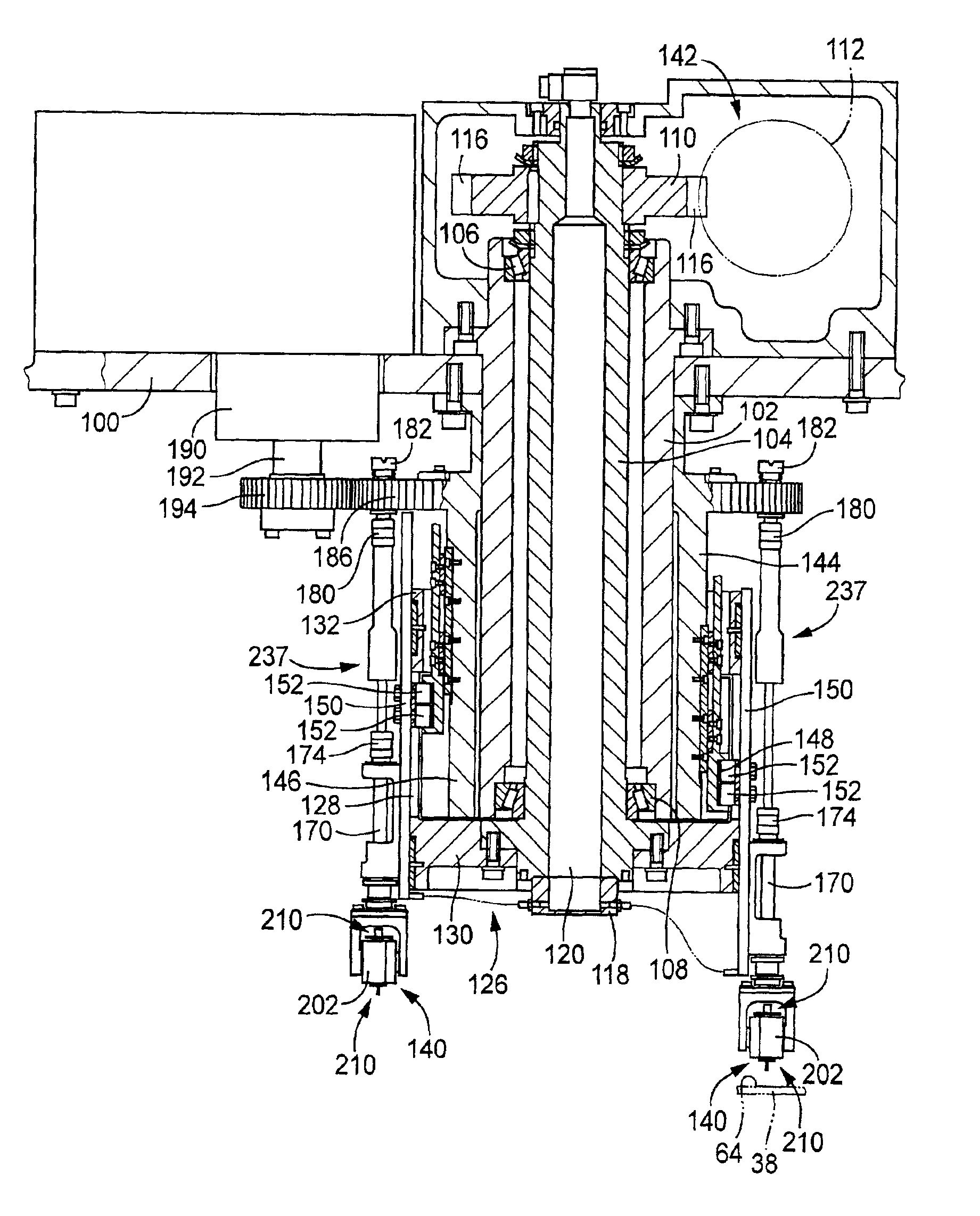
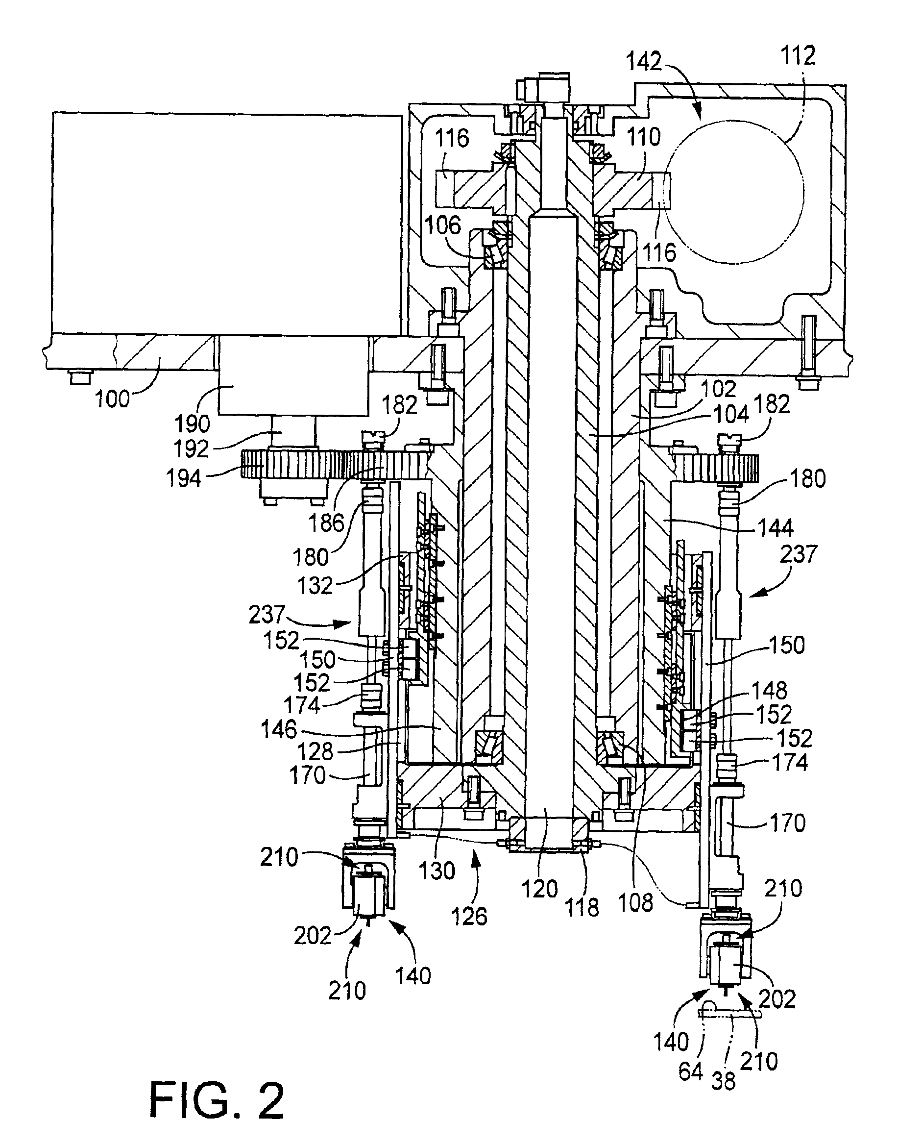
[0022]In the electric-component mounting system according to the above mode (2), the component-holding device is moved by the XY
robot to a predetermined component-mounting position on the printed-wiring board. In this case, the direction of the movement of the component-holding device to the component-mounting position and the pattern of control of the
moving speed of the component-holding device change depending upon the component-mounting position and are not constant for all of the electric components. Accordingly, the control target used to position the component-holding device is required to be determined depending upon the component-mounting position. Thus, the principle of this invention is applicable to the present mounting system wherein the component-holding head is moved to each component-mounting position. However, the application of the principle to this type of system requires a relatively complicated control. Where the component-holding device uses a suction
nozzle arranged to hold the electric component by suction under a negative pressure, for example, the acceleration and deceleration values of the suction
nozzle during its movement to the component-mounting position are desirably changed or controlled depending upon the
mass and / or the height dimension of the electric component, in order to prevent
dislocation of the electric component with respect to the suction
nozzle, or falling of the electric component from the suction nozzle, which
dislocation or falling may take place due to an
inertia. In this case, the pattern of control of the
moving speed of the component-holding device is changed or controlled by controlling the pattern of control of the operating speed of the XY
robot. A change of the pattern of control of the
moving speed of the component-holding device during its movement to a predetermined component-mounting position causes a change of the actual mounting position of the electric component, since the change of the pattern of control causes a change in the degree of elastic deformation of the component-holding device and a supporting device supporting the component-holding device, which occurs upon stopping of the component-holding device at the predetermined component-mounting position to
mount the electric component. In view of this fact, one of the different control targets for establishing the predetermined relative position between the component-holding device and the board-supporting device is selected depending upon the specific pattern of control of the operating speed of the XY
robot, that is, the specific pattern of control of the moving speed of the component-holding device, so that the positioning error of the electric component due to a varying degree of elastic deformation of the component-holding head and the supporting device can be reduced or prevented.
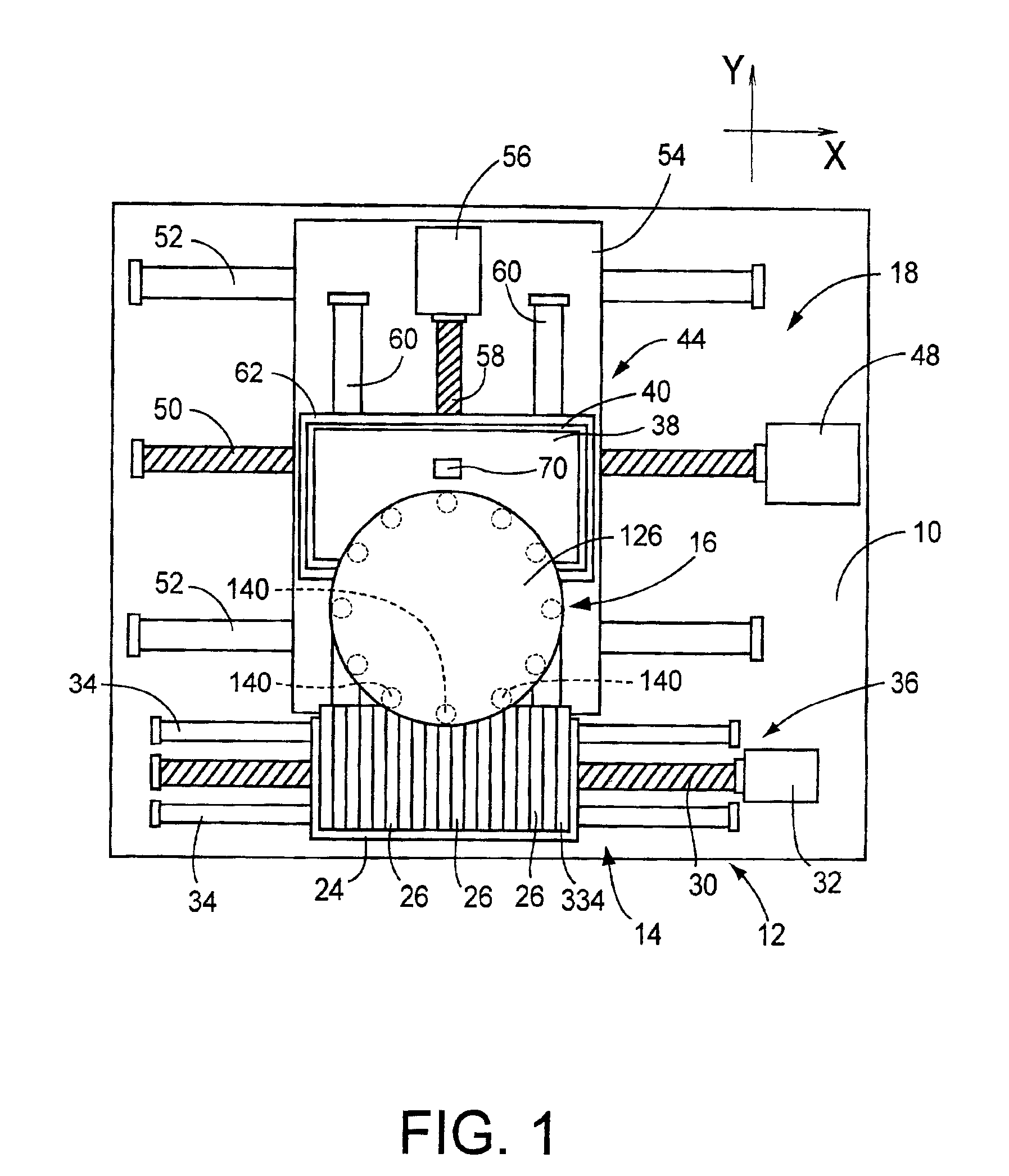
[0028]The electric-component mounting system according to the above mode (3) is usually arranged such that the component-holding members are be turned by the turning device at a comparatively high speed, while the printed-wiring board is moved by the board-positioning device at a comparatively
low speed. Accordingly, the electric component has a relatively large amount of positioning error due to elastic deformation of the corresponding component-holding member and the turning device upon stopping of the component-holding member following the movement by the turning device. This positioning error can be reduced or prevented by suitably selecting the control target used by the board-positioning device to position the printed-wiring board. Since the path of turning movement of each component-holding member by the turning device is held constant, the control target can be selected in a simpler manner than in the electric-component mounting system according to the above mode (2), which includes the XY robot. It is also noted that the mounting system according to the above mode (3) is generally operated at a higher speed, than the mounting system according to the above mode (2), so that the electric component mounted by the component-holding member has a relatively large amount of positioning error due to the above-indicated elastic deformation upon stopping of the component-holding member. In this respect, the positioning portion of the control device operable to select the suitable control target is particularly effective in the mounting system according to the above mode (3).
[0038]As the maximal rotating speed of the indexing body is increased, the
centrifugal force acting on each component-holding member (acceleration and deceleration values of the component-holding device in the radial direction of the turning device) is accordingly increased, and the vibration of the component-holding member in the radial direction is accordingly increased. As the deceleration value of the indexing body is increased, the vibration in the tangential direction of the turning device is accordingly increased. Accordingly, the positioning error of the electric component at the component-mounting position varies with at least one of the maximal rotating speed and deceleration value of the indexing body, although the positioning error also varies with the other factors relating to the control of the turning speed of the turning device. However, the positioning error of the electric component is not necessarily increased with an increase in the maximal rotating speed and deceleration value of the indexing body, presumably because the electric component is not necessarily mounted on the printed-wiring board at the moment when at least one of the vibrations in the above-indicated two directions has the
maximum amplitude, that is, the electric component may be mounted while the magnitude of the vibration or vibrations is being increased or reduced. It is also noted that the direction of the positioning error of the electric component is not constant. In view of the above, it is considered possible to improve the mounting accuracy of the electric component, by selecting the control target used to position the printed-wiring board, depending upon at least one of the maximal rotating speed and deceleration value of the indexing body.

