Controller of hybrid vehicle

a control system and hybrid technology, applied in the direction of electrical control, hybrid vehicles, non-mechanical valves, etc., can solve the problems of reducing the amount of regeneration energy, reducing the application range of this driving system to a variety of vehicles, and reducing the transmission efficiency of the power transmission system of this driving system. , to achieve the effect of improving the fuel consumption efficiency

Inactive Publication Date: 2005-10-11
HONDA MOTOR CO LTD
View PDF29 Cites 17 Cited by
  • Summary
  • Abstract
  • Description
  • Claims
  • Application Information

AI Technical Summary

Benefits of technology

[0027]According to the above aspect, it is possible to improve the fuel consumption efficiency by stopping the fuel supply to anomalous cylinders and ...

Problems solved by technology

However, the driving system having a clutch between the engine and the motor has a structure that has a problem in that the applicability of this driving system to a variety of vehicles is restricted because of the complicated structure of this system and because the transmission efficiency of the power transmission system of this driving system is degraded even when the vehicle is running.
The driving system in which the engine, the motor, and the transmission are connected in series has a p...

Method used


Image

  • Controller of hybrid vehicle
  • Controller of hybrid vehicle
  • Controller of hybrid vehicle

Examples


first embodiment

[0045]Hereinafter, the present invention is described with reference to the attached drawings.

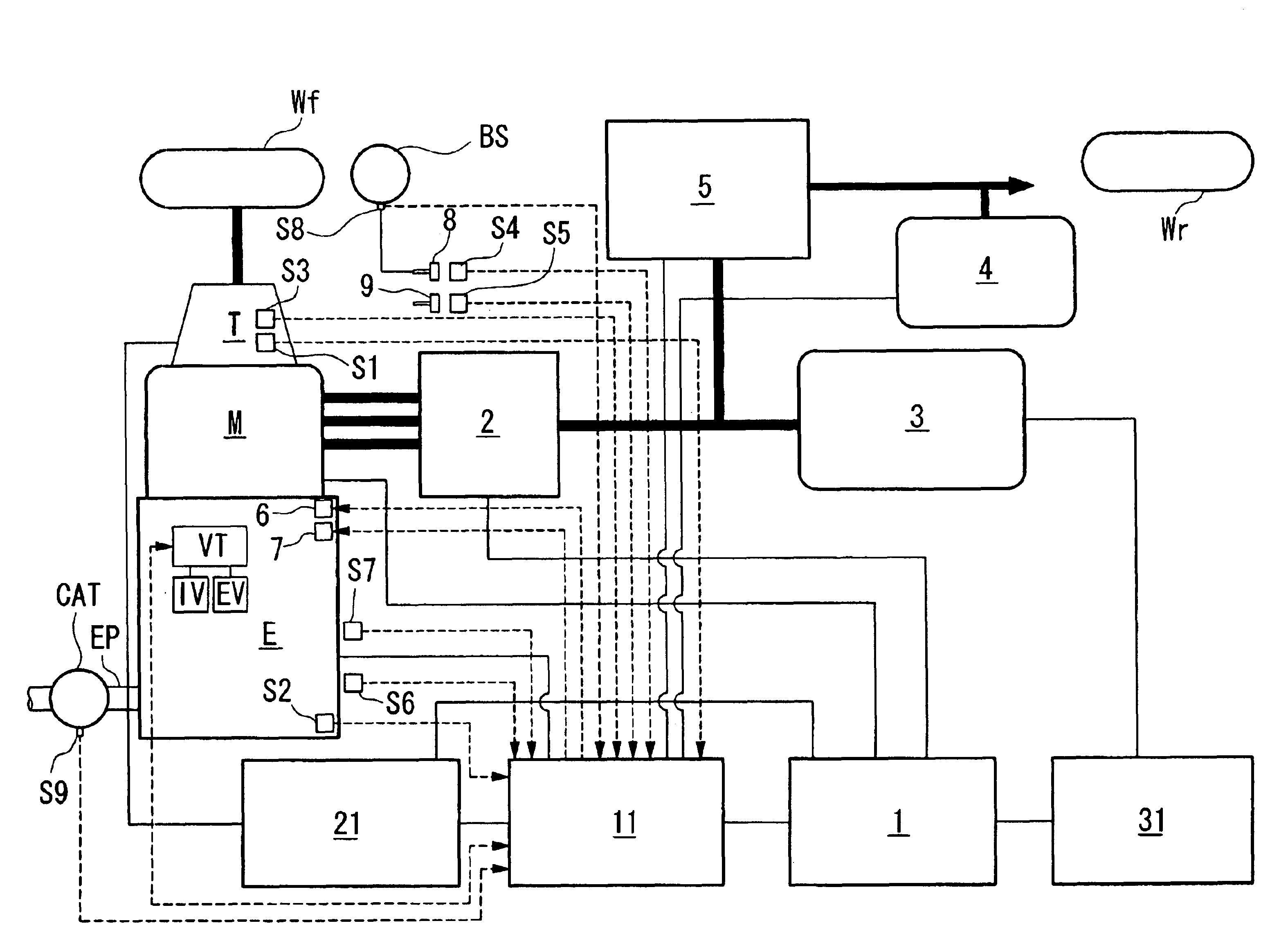
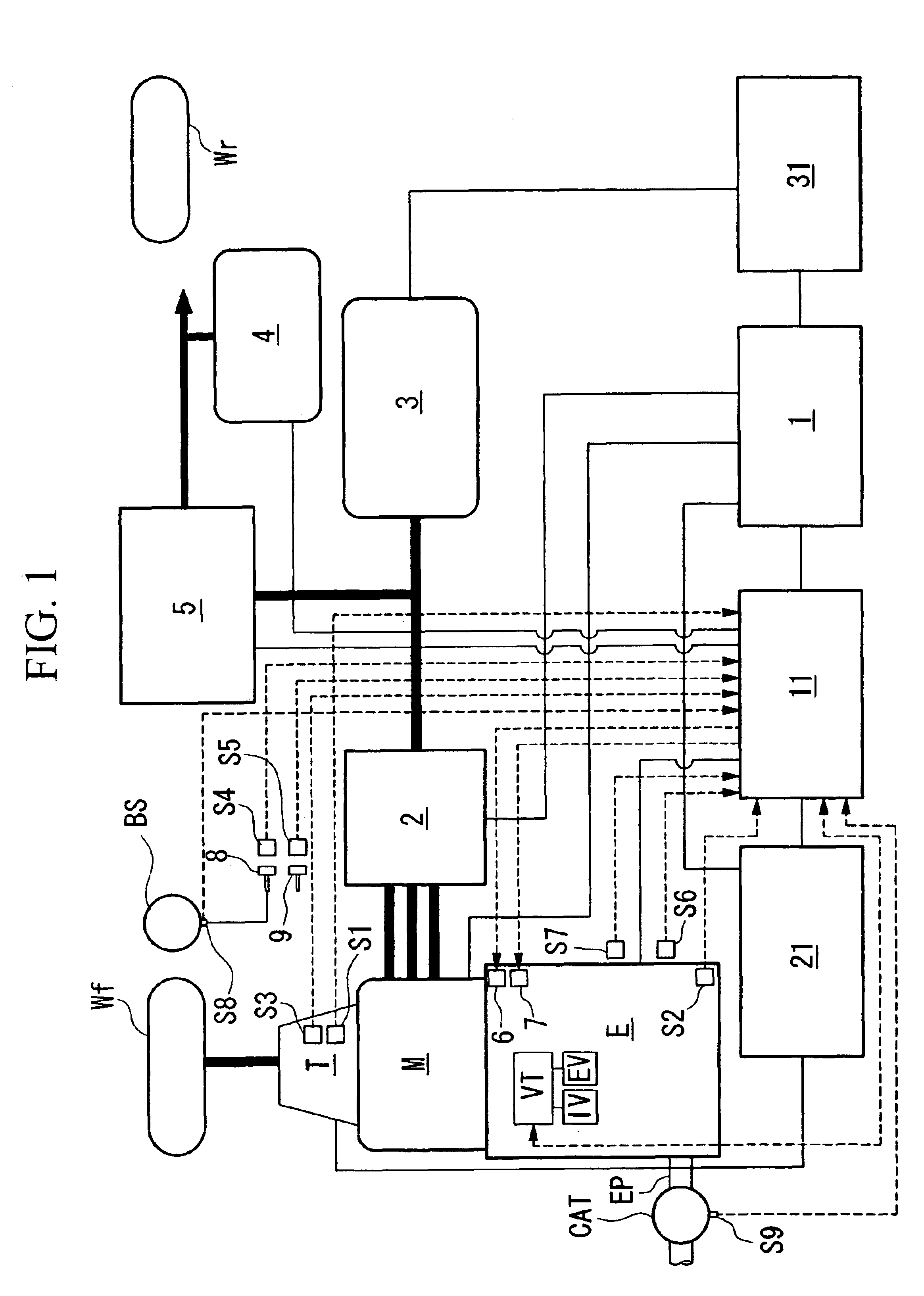
[0046]FIG. 1 is a schematic diagram showing the overall structure of the hybrid vehicle. As shown in FIG. 1, the driving system is constituted by connecting an engine E, a motor M, and a transmission T in series. Thus, a clutch is not provided between the engine E and the motor M. The driving force of both of the engine E and the motor M is transmitted to front wheels Wf and Wf as driving wheels through a transmission T such as an automatic transmission or a manual transmission. In contrast, when the driving force is transmitted from the front wheels during deceleration of the hybrid vehicle, the motor M operates as a generator which generates regenerative braking energy and the kinetic energy of the vehicle is recovered as electric energy. Note that the symbol Wr denotes a rear wheel.

[0047]The driving of the motor M and the regenerative operation by the motor M are conducted by a power dri...

second embodiment

[0192]Next, the present invention will be described with reference to FIGS. 15 to 17.

[0193]In the second embodiment, one cylinder out of four cylinders is configured not to carry out the cylinder pausing operation, and the other three cylinders are cylinders which can carry out the cylinder pausing operation. Note that the number of cylinders which can execute the cylinder pausing operation are not limited and the number can be more than one half of the total cylinders.

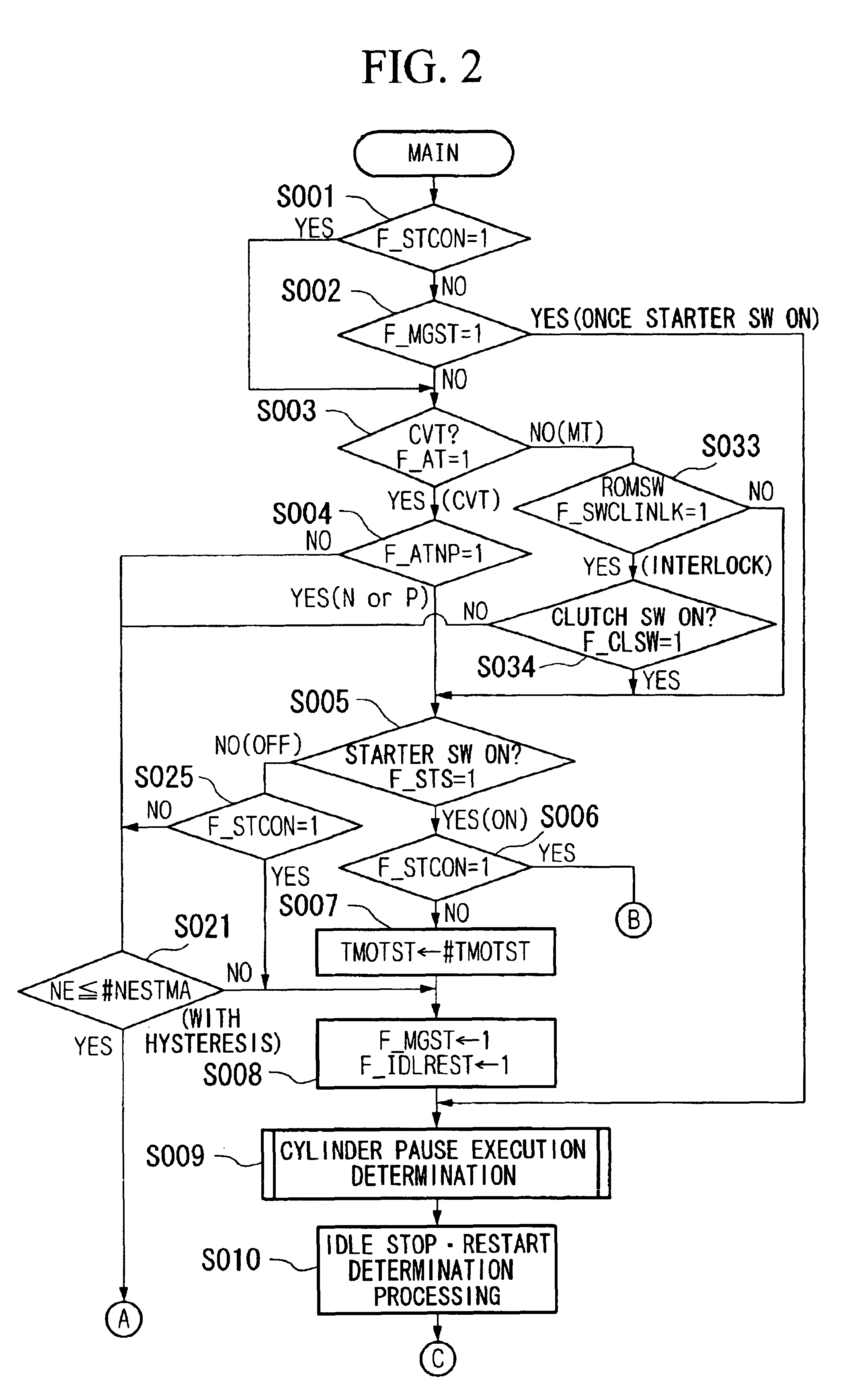
[0194]Thus, the other structure of the second embodiment is the same as that of the first embodiment, and the processing procedures shown in FIGS. 2 to 12 are also the same, so that the same components are denoted by the same reference numbers and their explanations are omitted.

[0195]In FIGS. 15 and 16, the engine E comprises three cylinders each provided with a variable valve timing mechanism VT (the same as the first embodiment) at the air intake side and the exhaust side for executing the cylinder pausing operation...


PUM


Abstract

A control device for a hybrid vehicle having an engine and a motor as driving sources for the vehicle, and when decelerating, the control device stops the fuel supply to the engine and generates energy by regenerative braking. The engine is a cylinder pause-type engine which is capable of switching between the all-cylinder driving state in which all of cylinders are operating, and a cylinder paused driving state in which all of the cylinders are paused, and the control device of the hybrid vehicle comprises a cylinder pause state determination device for determining whether the engine is in the all cylinder driving state or in a cylinder paused driving state and a regeneration amount supplementing device for supplementing the regeneration energy by the motor by use of the increment of the regeneration energy obtained during the cylinder pausing operation than that obtained during all cylinder driving state.

Description

BACKGROUND OF THE INVENTION[0001]1. Field of the Invention[0002]The present invention relates to a control system for a hybrid vehicle, and in particular, relates to a control system for a hybrid vehicle capable of improving the fuel consumption efficiency.[0003]2. Description of the Related Art[0004]Conventionally, hybrid vehicles, which carry motors as power sources for driving in addition to engines, are known. Hybrid vehicles are classified into serial hybrid vehicles and parallel hybrid vehicles. In parallel hybrid vehicles, the motor connected to the engine assists the rotation of the drive shaft of the engine while charging a power storage unit using the motor as a generator.[0005]In parallel hybrid vehicles, the motor assists the engine at the time of acceleration and a power storage unit such as a battery is charged by deceleration regeneration during deceleration, in order to maintain sufficient electrical energy in the power storage unit such as a batteries (hereinafter, ...

Claims


Application Information

Patent Timeline
IPC IPC(8): B60K6/04B60K6/00F01L1/26F02D17/00F02D17/02F02D41/32F02D41/36F02D13/04B60K6/20F01L13/00B60K6/485B60K6/54B60L50/16B60W10/06B60W10/08B60W20/00F02D13/02F02D13/06F02D29/02F02D41/02F02D41/04F02D45/00
CPCB60K6/48B60K6/485B60K6/543B60W10/06B60W10/18F01L1/022F01L1/267F02D13/04F02D17/02F02D41/0087F02N11/006F02N11/0818F02N11/10B60W20/00B60W2540/12B60W2550/12B60W2710/0605F01L2103/01F01L2105/00F01L2800/00F01L2800/13F02D41/123F02D2041/0012F02D2200/0406F02D2200/0802F02D2250/41F02N2200/023Y02T10/6221Y02T10/6226Y02T10/48B60W2555/20F01L2303/01F01L2305/00Y02T10/40Y02T10/62B60W30/18127B60W20/13
Inventor WAKASHIRO, TERUOTAKAHASHI, HIDEYUKIMATSUBARA, ATSUSHIKAMO, TOMOHARUSATO, TOSHIYUKINAKAMOTO, YASUO
Owner HONDA MOTOR CO LTD
Why Eureka
Try Eureka