Fluid-assisted medical devices, systems and methods

a technology of medical devices and fluids, applied in the field of electric surgical devices, systems and methods for use upon the body during surgery, can solve the problems of untargeted adjacent tissue, tissue desiccation, tissue sticking to the electrode, etc., and achieve enhanced electrical coupling, increased uniformity of electrical coupling therebetween, and enhanced electrical coupling

Inactive Publication Date: 2005-10-11
MEDTRONIC ADVANCED ENERGY
View PDF148 Cites 1538 Cited by
  • Summary
  • Abstract
  • Description
  • Claims
  • Application Information

AI Technical Summary

Benefits of technology

[0015]According to the present invention, electrosurgical devices, systems and methods are provided in which the electrical current paths, associated electrical resistance heating and ensuing thermal conduction heating are substantially limited to tissue within the jaws of the device, so as to inhibit, and preferably prevent, tissue damage outside the jaws due to thermal effects. More preferably, the electrical current paths, as well as current density, are concentrated within the confines and borders of two electrically insulated surfaces of the jaws and, even more preferably, within the medial portions of the electrically insulated surfaces.
[0018]According to the present invention, preferably the enhanced electrical coupling is provided by an electrically conductive fluid which couples between the tissue surface and the electrodes and increases the uniformity of the electrical coupling therebetween. In addition to inhibiting tissue damage as outlined above, this enhancement is particularly useful to counter poor electrical coupling associated with prior art dry devices, uneven and undulated tissue, shrinkage of treated tissue, desiccation of treated tissue and motion of the jaws while grasping tissue.
[0019]According to the present invention, electrosurgical devices, systems and methods are provided in which a portion of the electrical current, upon exiting from between the two electrically insulated surfaces, flows at least partially through the electrically conductive fluid, rather than through the tissue outside the electrically insulated surfaces, before reaching the counter electrode. According to the present invention, this will inhibit tissue damage outside the electrically insulated surfaces given the decrease in electrical current through the tissue and associated decrease in power in the tissue will correspondingly reduce the amount of resistance and conduction heating of the tissue.
[0025]According to the present invention, electrosurgical devices, systems and methods are provided in which removal of heat from and cooling of the tissue outside the electrically insulated surfaces is enhanced, so as to inhibit tissue damage outside the electrically insulated surfaces. Preferably, the enhanced cooling is provided by a fluid, particularly the electrically conductive fluid. More particularly, in the event a portion of the electrical current exiting from between the two electrically insulated surfaces flows through tissue outside the electrically insulated surfaces, thus heating the tissue outside the electrically insulated surfaces by resistance and conduction heating, the conductive fluid function as a heat sink to absorb and remove heat from the tissue and cool the tissue. Furthermore, it is an object of the present invention that the conductive fluid lubricates the tissue / electrode interface and the tissue / electrically insulated surface interface as to inhibit sticking thereto.
[0028]According to the present invention, using a fluid in the above manner inhibits, and preferably minimizes or prevents tissue damage (e.g. necrosis), and such undesirable effects as tissue sticking to electrodes, smoke generation, char formation and desiccation, to tissue outside a targeted tissue treatment site.

Problems solved by technology

Current dry tip RF electrosurgical devices can cause the temperature of tissue being treated to rise significantly higher than 100° C., thus exceeding the boiling temperature of inter-cellular water and resulting in tissue desiccation, tissue sticking to the electrodes, tissue perforation, char formation and smoke generation.
Undesirable results of such transmission to untargeted adjacent tissue include unintended thermal damage to the untargeted tissue.
The Hooven patent goes on to recite that “[t]hermal damage to adjacent structures can occur due to this spread of thermal energy outside the jaws of the instrument.
Because of the spread of thermal energy outside the jaws of the instrument, it is difficult to coagulate long sections of tissue, such as bowel, lung, or larger blood vessels, without significant lateral thermal spread.
Over-coagulation frequently occurs, resulting in tissue sticking to the jaws of the instrument.
When the jaws of the instrument are opened, if the tissue sticking is severe, the tissue can be pulled apart, thus adversely affecting hemostasis.”
However, the invention of the Hooven patent encounters certain difficulties.
Due to tissue irregularities, the surface of the tissue to be treated may be uneven or undulated with peaks and valleys.
Consequently, the area of electrical coupling of the tissue to the electrode surfaces can be limited to the isolated peaks in the tissue surface.
Hooven does not address or provide for this situation.
Another difficulty encountered with the Hooven invention is that it does not address or provide for a decreasing electrical coupling between the tissue and electrode surfaces upon tissue shrinkage and / or desiccation during treatment.
This difficulty is further exacerbated if the tissue is undulated as described above.
Another difficulty encountered with the Hooven invention is that it does not address or provide for dissipating heat from the insulating members.
Hooven does not address or provide how heat which may be conducted into the insulating members from the tissue between the two insulated surfaces is subsequently removed from the insulating members.

Method used


Image

  • Fluid-assisted medical devices, systems and methods
  • Fluid-assisted medical devices, systems and methods
  • Fluid-assisted medical devices, systems and methods

Examples


Embodiment Construction

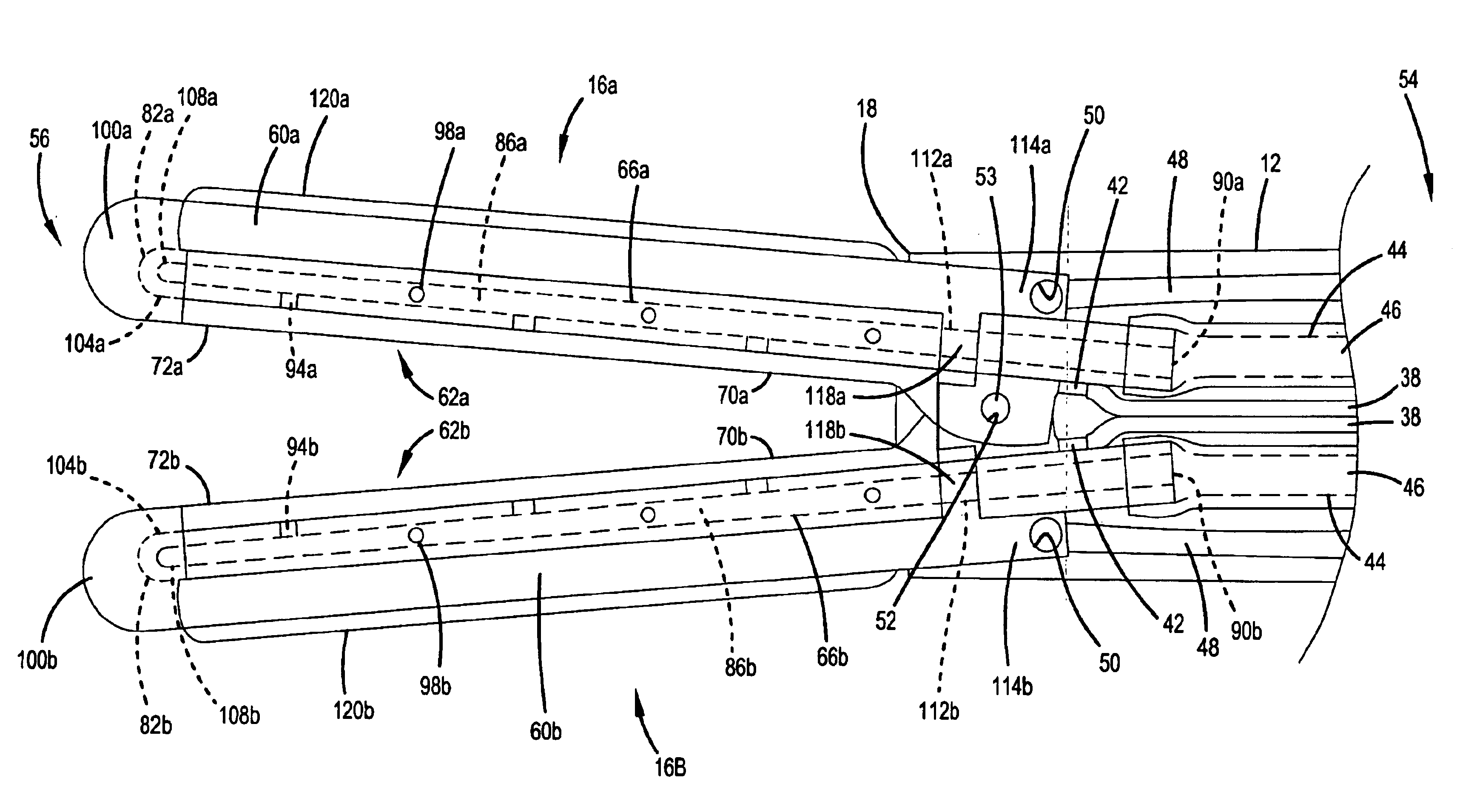
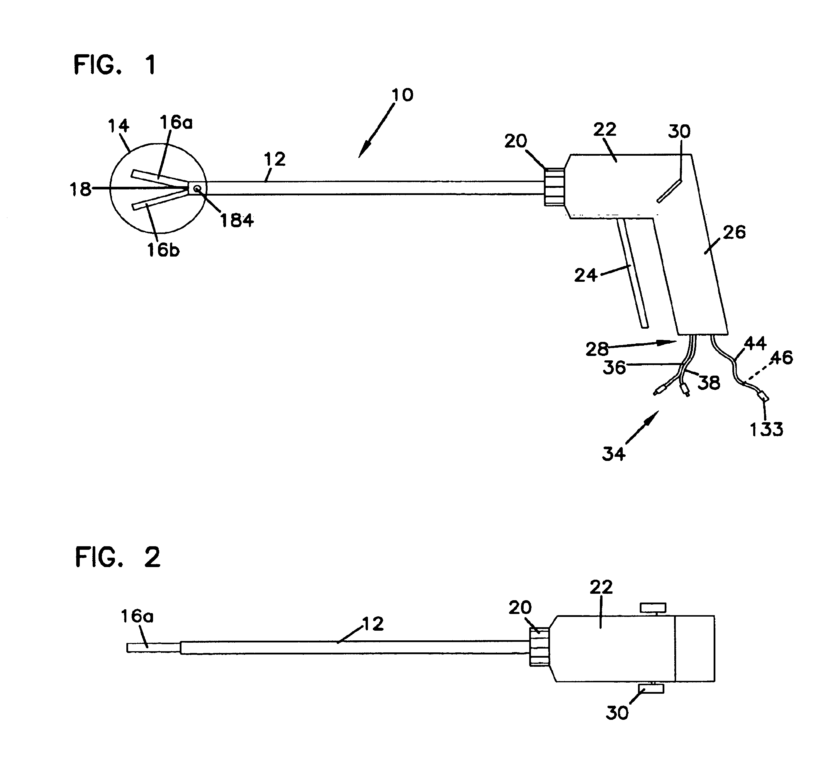
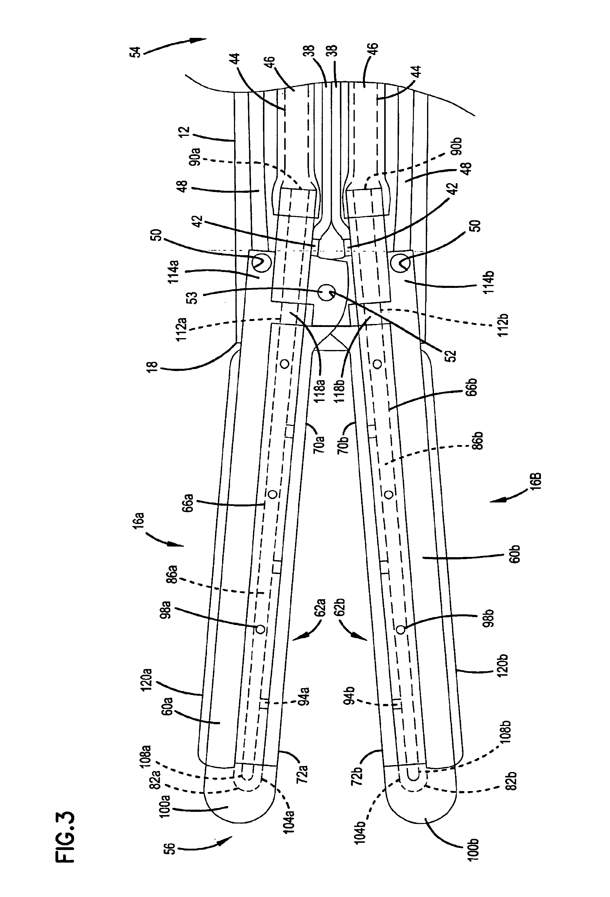
[0075]Throughout the present description, like reference numerals and letters indicate corresponding structure throughout the several views, and such corresponding structure need not be separately discussed. Furthermore, any particular feature(s) of a particular exemplary embodiment may be equally applied to any other exemplary embodiment(s) of this specification as suitable. In other words, features between the various exemplary embodiments described herein are interchangeable as suitable, and not exclusive. Also, from the specification, it should be clear that any use of the terms “distal” and “proximal” are made in reference to the user of the device, and not the patient.

[0076]An exemplary electrosurgical device according to the present invention will now be described in detail. The electrosurgical device may be used with the system of the invention to be described herein. However, it should be understood that the description of the combination is for purposes of illustrating the...


PUM


Abstract

Surgical devices, systems and methods for treating tissue are provided. An exemplary surgical device comprises a tip portion including first and second jaws each having a tissue grasping surface, at least one of the jaws being movable toward the other jaw. The tissue grasping surface of each jaw has includes an electrically insulative surface. The device also includes first and second electrodes connectable to different terminals of an RF generator to generate electrical current flow therebetween, with each of the electrodes having an electrode surface. One of the electrode surfaces is located on one of the jaws separated from one edge of the tissue grasping surface, and the other of the electrode surfaces is located on one or the other of the jaws separated from the other edge of the tissue grasping surface. The device also includes at least one fluid passage being connectable to a fluid source.

Description

FIELD[0001]This invention relates generally to the field of medical devices, systems and methods for use upon a body during surgery. More particularly, the invention relates to electrosurgical devices, systems and methods for use upon tissues of a human body during surgery, particularly open surgery and minimally invasive surgery such as laparoscopic surgery.BACKGROUND[0002]The application of heat to tissue, typically from a flame heated metal object, has been used for centuries to cauterize bleeding wounds. In cauterization, the essential mechanism behind tissue treatment involves raising the temperature of the bleeding tissue by conductive heat transfer from the heated metal object. In order to arrest bleeding from the tissue's severed blood vessels, the tissue is heated adequately to shrink certain tissue proteins, such as collagen, thus closing the blood vessels and ultimately leading to blood vessel thrombosis.[0003]Apart from shrinkage, the application of compressive force fro...

Claims


Application Information

Patent Timeline
Patent Type & Authority Patents(United States)
IPC IPC(8): A61B18/14A61B18/00A61B17/00A61B18/12A61B18/08A61B19/00
CPCA61B18/14A61B18/1442A61B18/1445A61B17/32A61B18/1206A61B2017/00022A61B2018/00011A61B2018/00029A61B2018/00035A61B2018/00065A61B2018/00196A61B2018/00404A61B2018/00589A61B2018/00595A61B2018/00601A61B2018/0063A61B2018/00702A61B2018/00744A61B2018/00779A61B2018/00791A61B2018/00809A61B2018/00875A61B2018/126A61B2018/1412A61B2018/1417A61B2018/1422A61B2018/1455A61B2018/1472A61B2018/1861A61B2019/305A61B2019/461A61B2019/465A61B2218/002A61B2090/035A61B2090/061A61B2090/065
Inventor MCCLURKEN, MICHAEL E.LIPSON, DAVIDOYOLA, E. ARNOLD
Owner MEDTRONIC ADVANCED ENERGY
Why Eureka
Try Eureka