Detachable device with electrically responsive element

a technology of responsive elements and detachable devices, which is applied in the field of detachable devices including electrically responsive elements, can solve the problems of reduced supply of oxygen and nutrients to the cells, difficulty in controlling heat delivery methods, and hemorrhage, and achieves more uniform heating of embolic devices. , the effect of consistent performan

Inactive Publication Date: 2005-10-11
BOSTON SCI SCIMED INC
View PDF19 Cites 88 Cited by
  • Summary
  • Abstract
  • Description
  • Claims
  • Application Information

AI Technical Summary

Benefits of technology

[0007]One aspect of the invention involves a detachable thermo-sensitive embolic device that utilizes thermo-resistive heating to cause more uniform heating of the embolic device and more consistent performance than using warm saline to control heating of an embolic device. This aspect allows electrical heating of the detachable thermo-sensitive embolic device to expand the device in an aneurysm for embolization. In addition, the embolic device is connected to a delivery device by a detachable joint, thereby enabling the embolic device to be deployed within a target treatment region within a patient, e.g., within an aneurysm. In one embodiment, the detachable joint may be an electrolytically erodible joint, allowing electrical heating to electrolytically detach the device to deploy the device into the aneurysm. In other embodiments, the detachable joint may include one or more mechanical connectors to detachably connect the embolic device to the delivery device.

Problems solved by technology

If the aneurysm ruptures, a hemorrhage occurs.
This can compress and irritate the surrounding blood vessels, resulting in a reduced supply of oxygen and nutrients to the cells, possibly causing a stroke.
Warm saline injections may be used to deliver localized heat to these devices, but this method of heat delivery may be difficult to reproduce in a controllable manner.

Method used


Image

  • Detachable device with electrically responsive element
  • Detachable device with electrically responsive element
  • Detachable device with electrically responsive element

Examples


Embodiment Construction

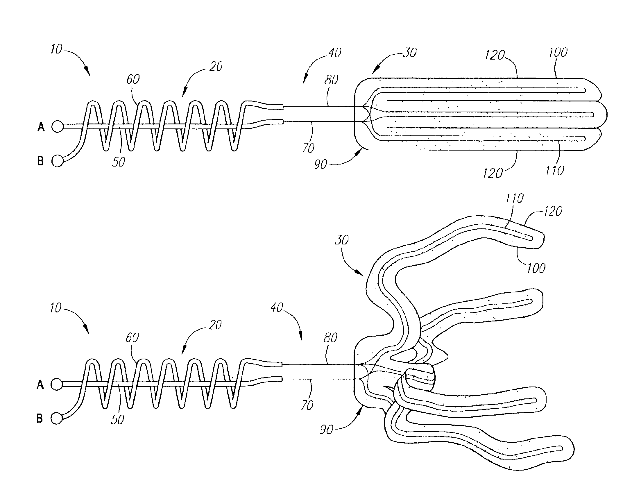
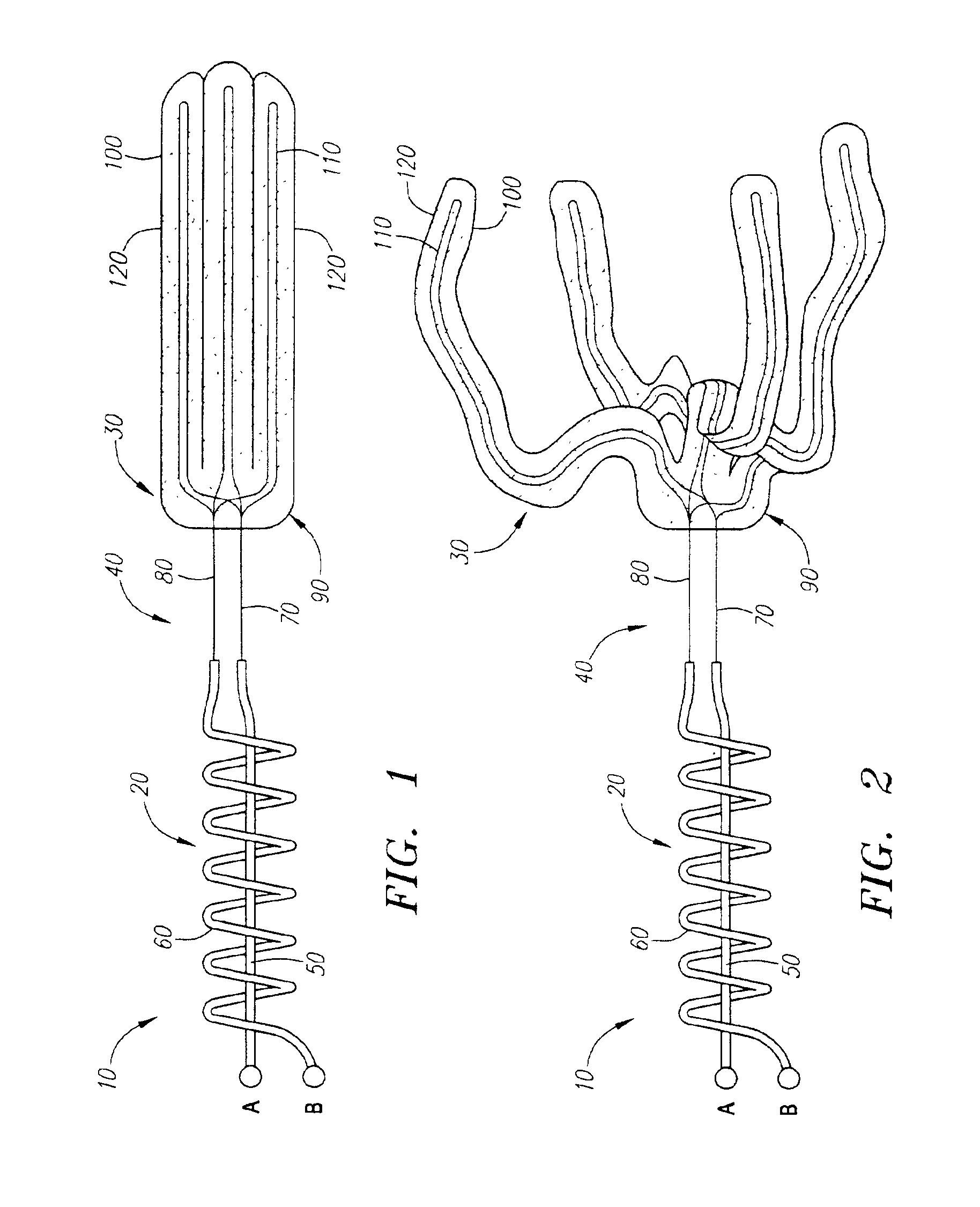
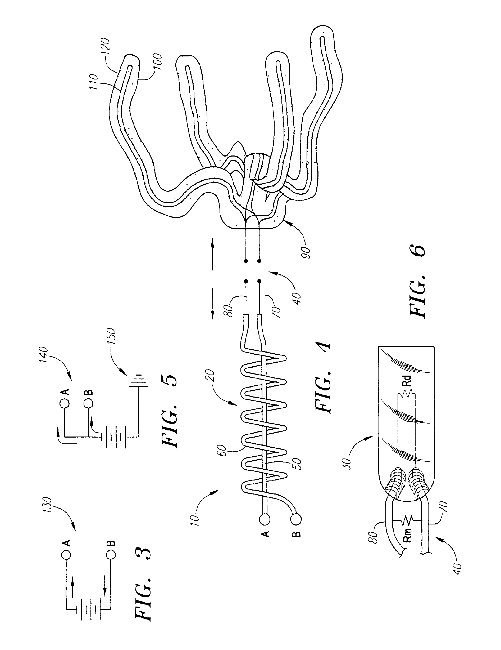
[0030]With reference to FIG. 1, an endovascular device assembly 10 is shown that includes a delivery member 20 and a detachable, thermo-resistive, expandable, embolic device 30. In the embodiment shown, the embolic device 30 is joined to the delivery member 20 by an electrolytic sacrificial joint 40. The device assembly 10 may be used for embolizing an aneurysm, although the device assembly 10 may also be adaptable for treating other conditions, such as endovascular occlusions in arteries, veins, vascular malformations, and arteriovenous fistulas. The device assembly 10 may also be used for forming an occlusion in other areas of a mammalian body, or for other purposes or applications. For example, the device assembly 10 may include one or more detachable, electrically responsive elements other than the detachable, thermo-resistive, expandable, embolic device 30 such as a microelectromechanical system (MEMS), an electrically stimulated contractile element, a light emitting diode, a p...


PUM


Abstract

An endovascular device assembly includes a delivery member to deliver the assembly endoluminally to an aneurysm, a detachable endovascular device including a thermo-resistive element to deliver heat to the device by passing a first electrical current through the thermo-resistive element, whereupon the device expands to a predetermined shape. The endovascular device is connected to the delivery member by a detachable joint, such as an electrolytic sacrificial joint that separates by passing a second electrical current therethrough, to deploy the device within the aneurysm to promote embolization.

Description

FIELD OF THE INVENTION[0001]The invention relates generally to a detachable device including an electrically responsive element, and, in particular, to an electrolytically or mechanically detachable endovascular device including a thermo-resistive element.BACKGROUND[0002]Like all parts of the body, the brain is composed of living cells that require a blood supply to provide oxygen and nutrients. A hemorrhage in a blood vessel in the brain or in the space closely surrounding the brain is a common cause of strokes. Hemorrhage refers to bleeding into the brain, usually because of a problem with a blood vessel, for example, an aneurysm.[0003]An aneurysm is an abnormal bulging and / or weakening of a blood vessel wall. The wall may smoothly bulge outwardly in all directions (a fusiform aneurysm) or it may form a sack arising from one wall (a saccular aneurysm). If the aneurysm ruptures, a hemorrhage occurs. This can compress and irritate the surrounding blood vessels, resulting in a reduce...

Claims


Application Information

Patent Timeline
Patent Type & Authority Patents(United States)
IPC IPC(8): A61B17/12A61B17/00
CPCA61B17/12022A61B17/12113A61B17/12172A61B2017/1205A61B2017/12063
Inventor PORTER, STEPHEN CHRISTOPHER
Owner BOSTON SCI SCIMED INC
Why Eureka
Try Eureka