Microstrip antenna array with periodic filters for enhanced performance

Inactive Publication Date: 2005-10-11
VEONEER US LLC
View PDF11 Cites 67 Cited by
  • Summary
  • Abstract
  • Description
  • Claims
  • Application Information

AI Technical Summary

Benefits of technology

[0013]One aspect of the present invention is an automotive sensor unit comprising two microstrip antenna arrays wherein the microstrip antenna arrays have a measured isolation with respect to each other of at least −30 dB in the frequency bandwidth of operation for an HRR sensor (22 to 26 GHz). More preferably, a measured isolation of the antenna arrays with respect to each other of at least −40 dB, or even more preferably of at least −50 dB, can be obtained. In a preferred embodiment, the antenna unit is formed in the shape of a hollow box, and comprises (a) a substrate forming the front side of the antenna unit, (b) a

Problems solved by technology

Microstrip antenna arrays operate using an unbalanced conducting strip suspended above a ground plane.
One problem that arises using this type of antenna design is that the transmit and receive antenna arrays are not perfectly isolated from each other.
There is some level of RF signal leakage between the two antenna arrays, either through the air or through the substrate material.
The leakage through the substrate is caused by undesired surface wave propagation.
This coupling effect between the two antenna arrays lowers antenna gain and reduces performance of the radar sensor.
First, the addition of a metal wall 11 in the antenna unit 10 consumes additional space and is cumbersome.
As antenna units are becoming increasingly smaller, it is undesirable to introdu

Method used


Image

  • Microstrip antenna array with periodic filters for enhanced performance
  • Microstrip antenna array with periodic filters for enhanced performance
  • Microstrip antenna array with periodic filters for enhanced performance

Examples


Embodiment Construction

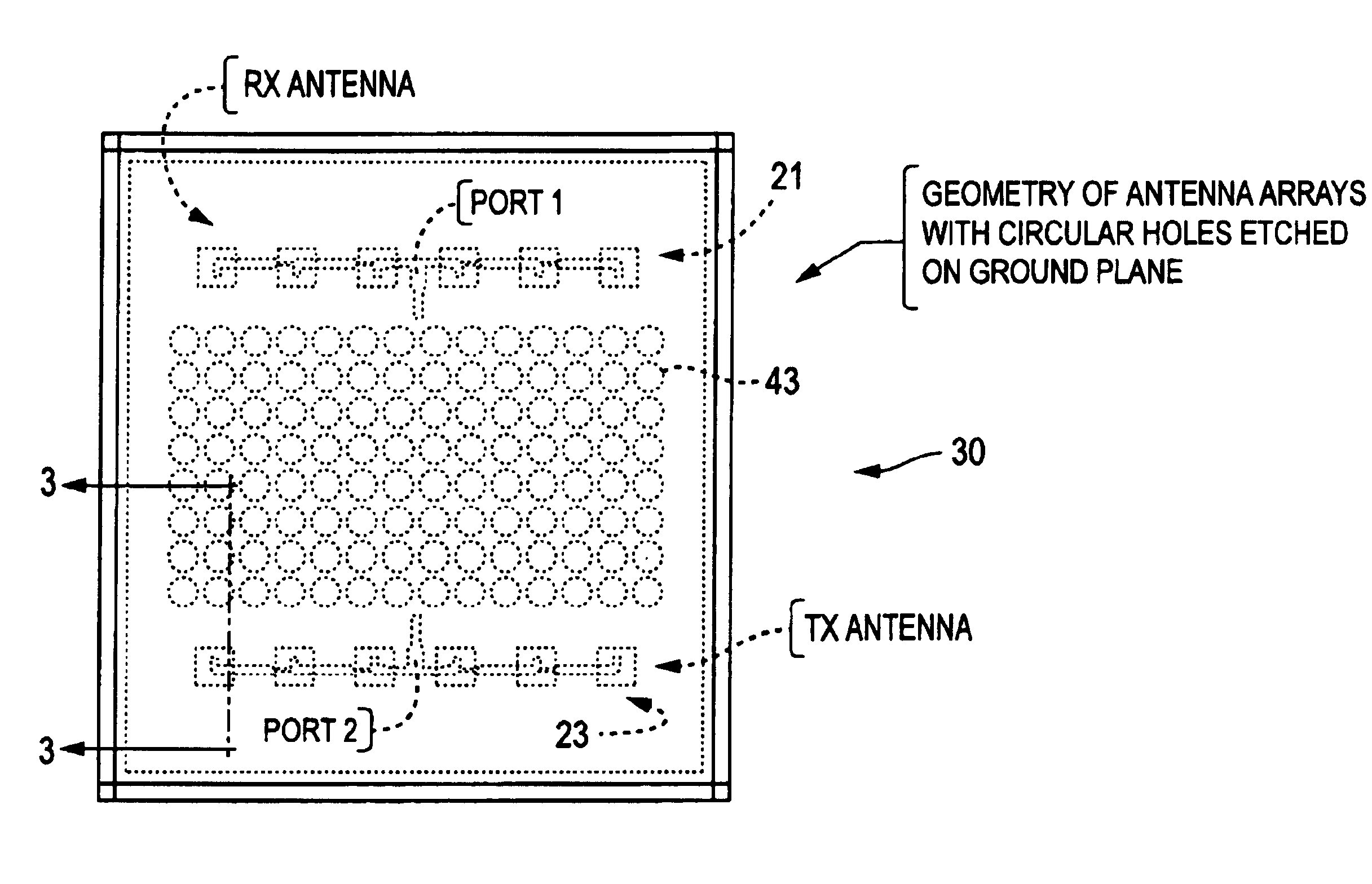
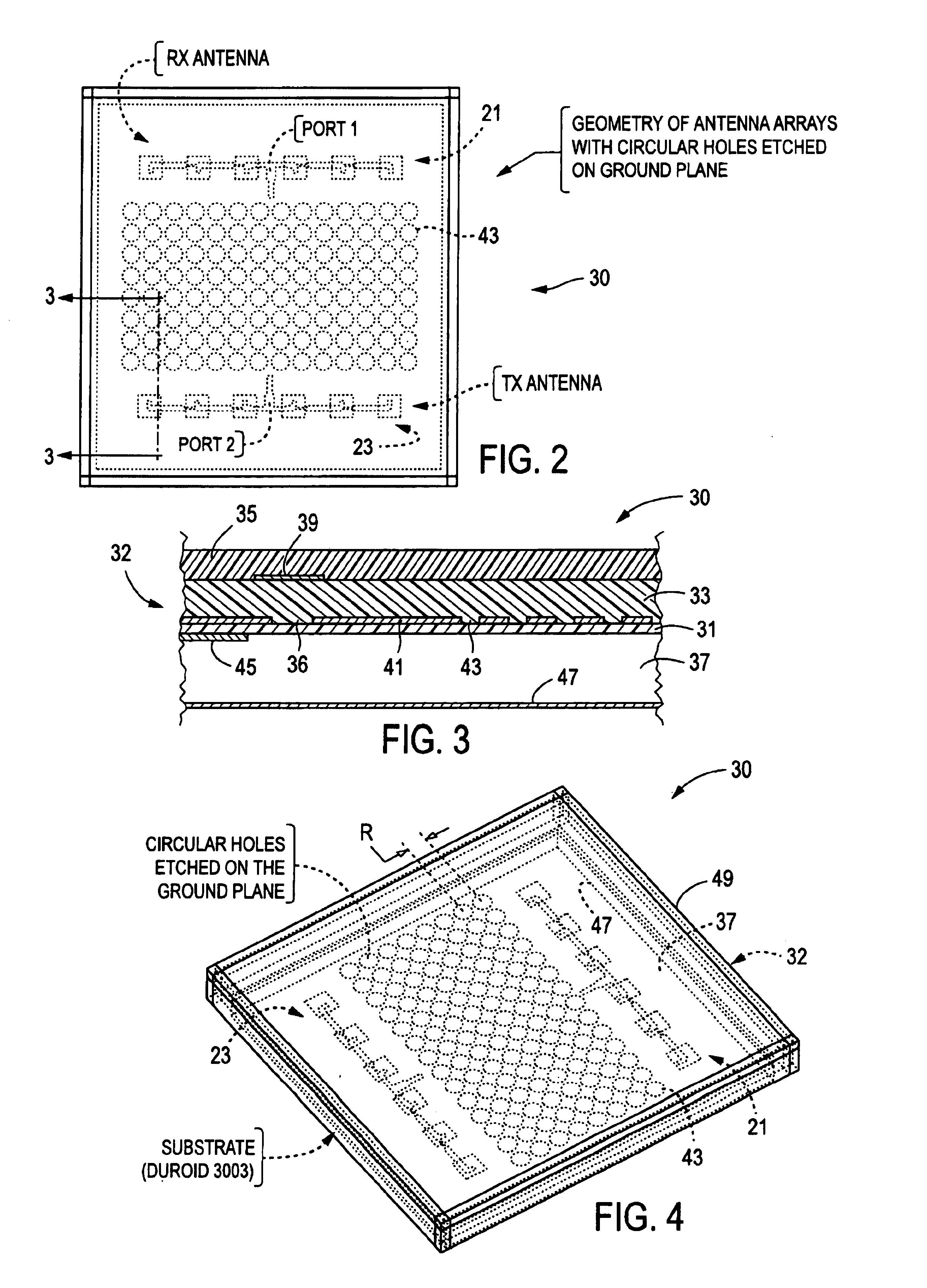
[0023]Referring to FIG. 2, a top view of a preferred embodiment of an antenna unit 30 in accordance with the present invention is shown. The antenna unit 30 contains a transmit slot-coupled microstrip antenna array (TX antenna) 21 and a receive slot-coupled mictrostrip antenna array (RX antenna) 23. The embodiment illustrated in FIG. 2 contains two slot coupled microstrip antenna arrays, although the invention is not limited to units having two slot-coupled microstrip antenna arrays. The invention may be practiced with antenna units comprising any number of slot coupled microstrip antenna arrays, or comprising any number of other types of microstrip antenna arrays, or units comprising a combination of both.

[0024]FIG. 3 shows a cross-section of the antenna unit layers shown in FIG. 2, as viewed along cut-line 3—3. The elements within the antenna unit 30 are formed on a multi-layer substrate 32. Each slot coupled microstrip antenna array comprises a feed microstrip 45 and at least one...


PUM


Abstract

An antenna unit formed in the shape of a hollow box comprising (a) a substrate forming the front side of the antenna unit, (b) a first microstrip antenna array formed on the substrate, (c) a second microstrip antenna array formed on the substrate, (d) a ground plane forming the rear side of the antenna unit, and (e) a plurality of periodic filters formed on the ground plane. The periodic filters are formed by etching a series of circular patterns, or holes, through the ground plane. The periodic stop band filters provide for improved isolation between the microstrip antenna arrays, without the need for adding additional costly or space consuming components.

Description

FIELD OF THE INVENTION[0001]The present invention relates to antennas, and more specifically to microstrip antenna arrays enhanced with periodic filters.BACKGROUND OF THE INVENTION[0002]The use of complex electronic systems in automobiles has increased dramatically over the past several years. Radar systems have been used in advanced cruise control systems, collision avoidance systems, and hazard locating systems. For example, systems are available today that inform the driver if an object (e.g. child's bicycle, fire hydrant) is in the vehicle's path even if the object is hidden from the driver's view.[0003]Systems such as these utilize small radar sensor modules that are mounted somewhere on the automobile (e.g., behind the front grill, in the rear bumper). The module contains one or more antennas for transmitting and receiving radar signals. These devices work by transmitting radio frequency (RF) energy at a given frequency. The signal is reflected back from any objects in its pat...

Claims


Application Information

Patent Timeline
IPC IPC(8): H01Q1/00H01Q1/52H01Q9/04H01Q21/06H01Q15/00H01Q21/00H01Q17/00H01Q13/08
CPCH01Q1/523H01Q9/0457H01Q21/0075H01Q21/065H01Q15/0013
Inventor CHANNABASAPPA, ESWARAPPAKOLAK, FRANKANDERSON, RICHARD ALAN
Owner VEONEER US LLC
Why Eureka
Try Eureka