Exposure apparatus

a technology of exposure apparatus and purge chamber, which is applied in the direction of microlithography exposure apparatus, printers, instruments, etc., can solve the problems of low throughput and decrease the throughput, and achieve the effect of shortening the time required for purging

Inactive Publication Date: 2005-10-11
CANON KK
View PDF40 Cites 30 Cited by
  • Summary
  • Abstract
  • Description
  • Claims
  • Application Information

AI Technical Summary

Benefits of technology

[0008]The present invention has been made in consideration of the above situation, and has as its object to shorten a time required to purge, with inert gas, gas in an optical path space including a space through which light passes, such as a space between a projection optical system and a substrate, a space between an illumination optical system which illuminates a mask (e.g., a reticle) and a mask stage which holds the mask, and a space between the mask stage and the projection optical system.
[0009]To achieve the above object, according to the present invention, there is provided an exposure apparatus which projects and transfers a pattern formed on a mask to a substrate by using exposure light, characterized by comprising a shielding member which surrounds a side plane of an optical path space including a space through which exposure light passes, and a gas supply portion which supplies inert gas to the optical path space surrounded by the shielding member, wherein the shielding member has a passage which makes the optical path space communicate with an ambient space. This arrangement can increase, e.g., the exhaust efficiency of gas which stays in an optical path space surrounded by the shielding member. As a result, the purge time of inert gas can be shortened.
[0010]According to a preferred aspect of the present invention, the passage is formed at a portion where a flow velocity of inert gas supplied from the gas supply portion decreases unless the passage is formed. Since the passage is formed at the portion where the flow velocity may decrease, a flow path can be formed at this portion to shorten the purge time.

Problems solved by technology

This results in low throughput.
The same problem occurs when inert gas is supplied to the vicinity of a reticle.
Also, for the reticle, the exposure apparatus requires several seconds until the oxygen concentration in a space surrounded by shielding members decreases, which decreases the throughput.

Method used


Image

  • Exposure apparatus
  • Exposure apparatus
  • Exposure apparatus

Examples


first embodiment

[First Embodiment]

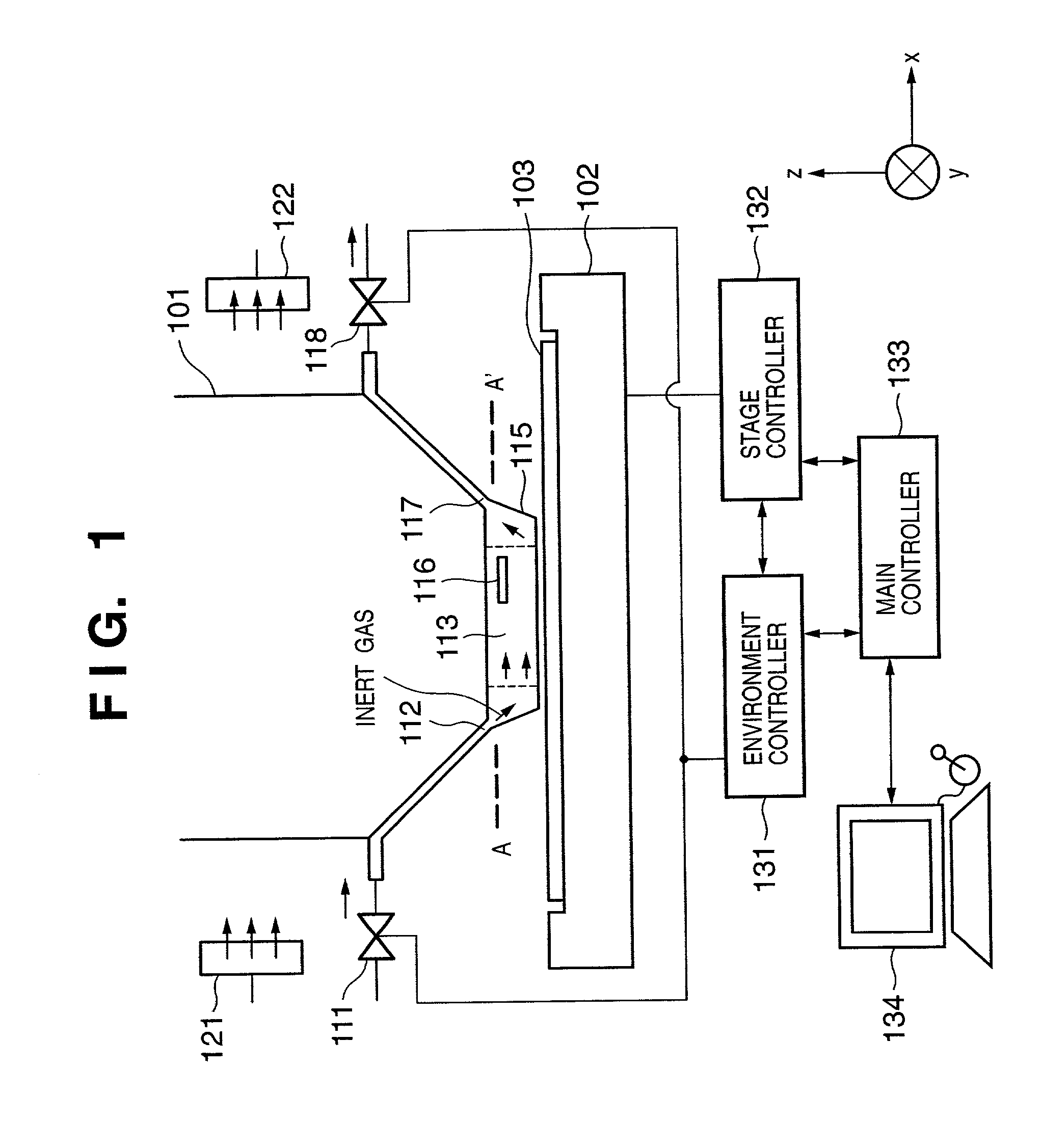
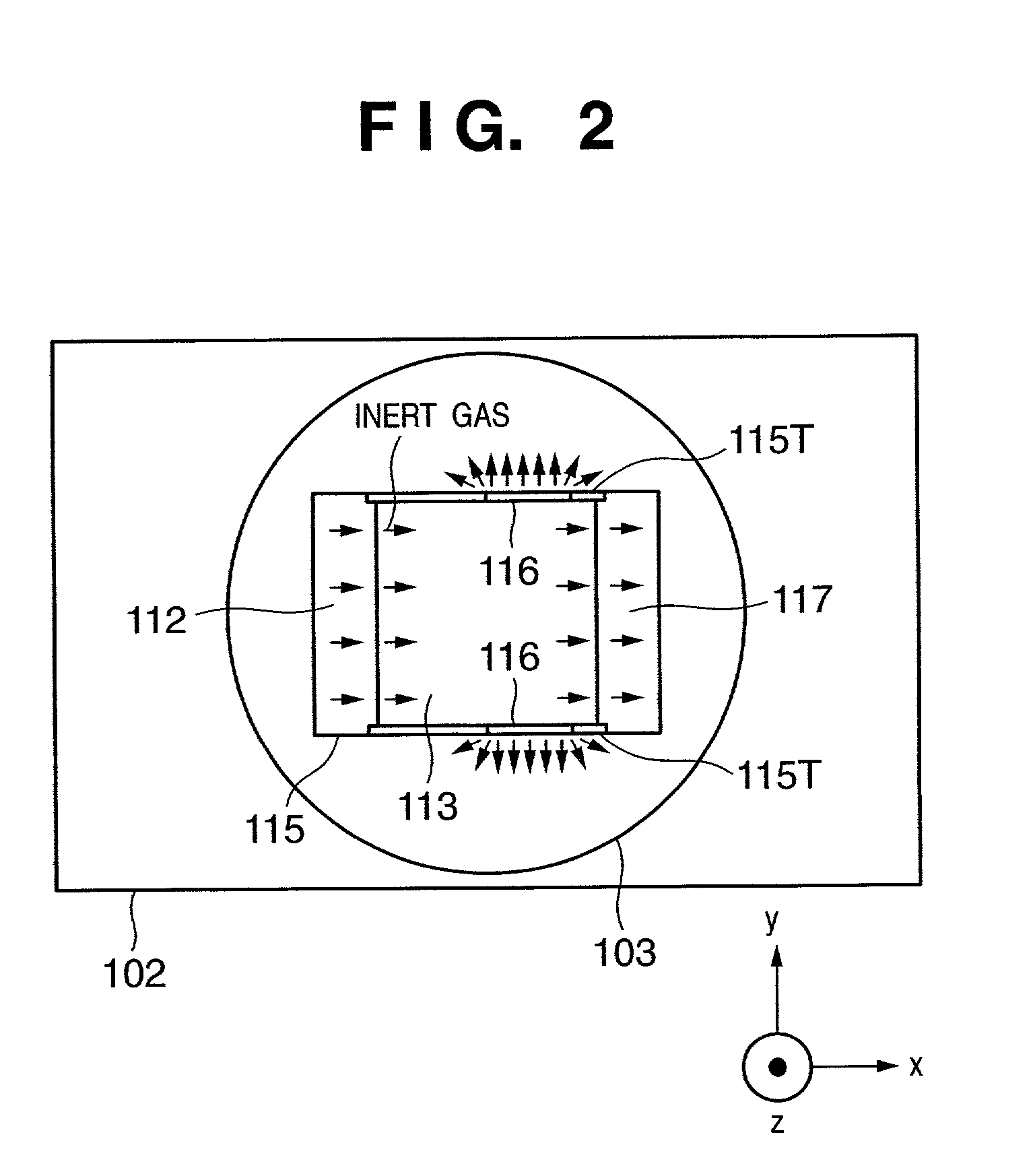
[0070]FIGS. 1 and 2 are views showing part of an exposure apparatus according to the first embodiment of the present invention. FIG. 1 is a schematic view showing the lower part of the projection optical system (lens barrel) of the exposure apparatus, the vicinity of a wafer, and a control system. FIG. 2 is a plan view when viewed downward from the line A–A′ in FIG. 1.

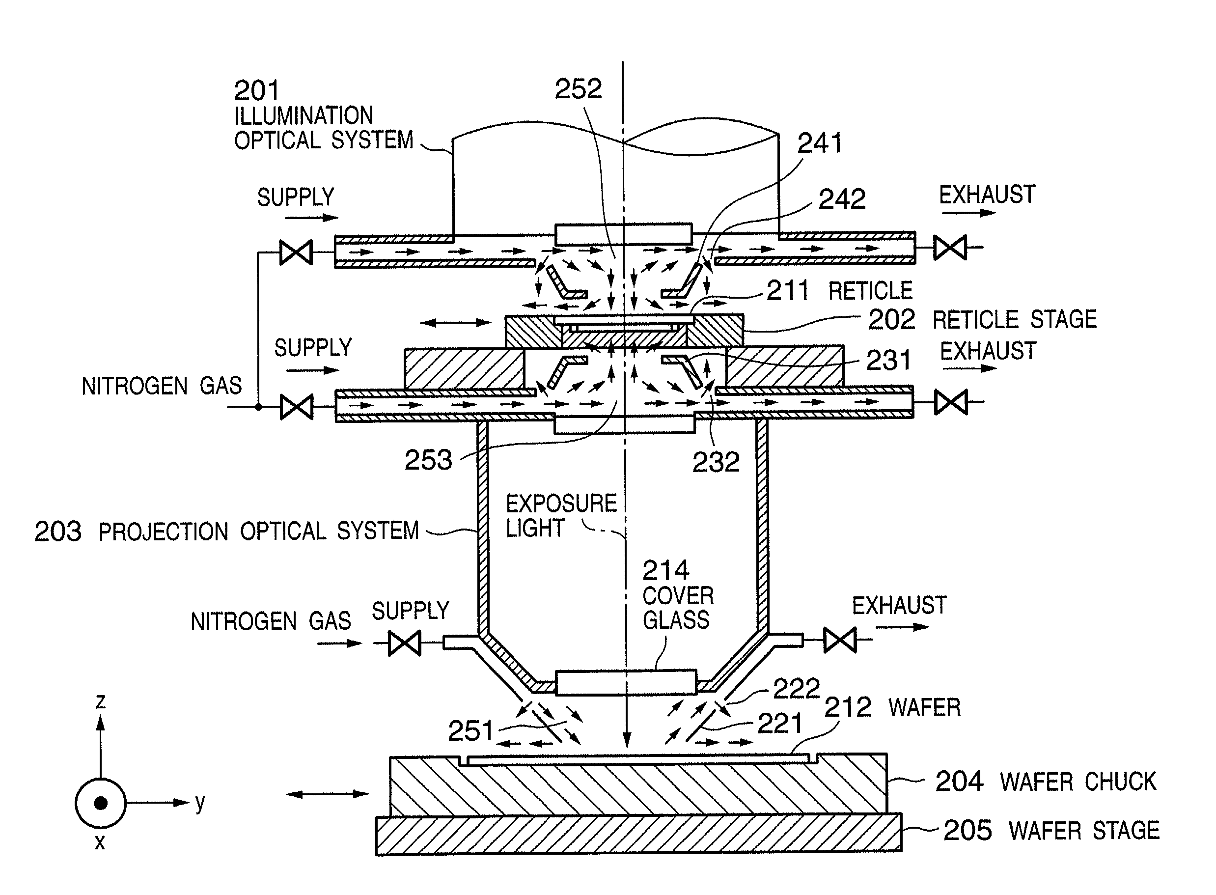
[0071]The exposure apparatus comprises a light source (not shown), such as an F2 excimer laser, which generates a short-wavelength laser beam as illumination light. Illumination light (exposure light) generated by the light source uniformly illuminates a reticle (mask) via a proper illumination optical member. Light (exposure light) having passed through the reticle reaches the surface of a wafer 103 set on a wafer stage 102 via various optical members which constitute a projection optical system 101. The light forms the reticle pattern image on the surface of the wafer 103.

[0072]The wafer stage 102 w...

second embodiment

[Second Embodiment]

[0081]FIGS. 3 and 4 are views showing part of an exposure apparatus according to the second embodiment of the present invention. FIG. 3 is a schematic view showing the lower part of the projection optical system (lens barrel) of the exposure apparatus and the vicinity of a wafer. FIG. 4 is a plan view when viewed downward from the line A–A′ in FIG. 3. FIG. 3 does not illustrate building components 131 to 134 in FIG. 1 for descriptive convenience.

[0082]In the second embodiment, first and second air supply ports 143 and 144 which supply inert gas to an optical path space 113 are arranged at positions opposite to each other via the exposure region (optical path space). The optical path space 113 receives inert gas via a first air supply valve 141 and the first air supply port 143, and via a second air supply valve 142 and the second air supply port 144 arranged at a position opposite to the first air supply port 143.

[0083]When the first and second air supply ports 14...

third embodiment

[Third Embodiment]

[0088]FIGS. 6 to 8 are views showing part of an exposure apparatus according to the third embodiment of the present invention. FIG. 6 is a schematic view showing the lower part of the projection optical system (lens barrel) of the exposure apparatus and the vicinity of a wafer. FIG. 7 is a plan view when viewed downward from the line B–B′ in FIG. 6. FIG. 8 is a view showing the structure of a shielding member. FIG. 6 does not illustrate building components 131 to 134 in FIG. 1 for descriptive convenience.

[0089]The first and second embodiments shorten the purge time by forming a passage (opening) at the upper portion of a shielding member. The structure in which the passage is formed at the upper portion of the shielding member is preferable for shortening the exhaust time, but is readily influenced by an ambient atmosphere. In the third embodiment, a passage is formed at the lower portion of a shielding member instead of forming the passage at the upper portion of ...


PUM

PropertyMeasurementUnit
wavelengthaaaaaaaaaa

Abstract

An exposure apparatus which projects a pattern formed on a mask onto a substrate by using exposure light. The apparatus includes a shielding member which surrounds a light path space through which exposure light passes and has a passage which makes the light path space communicate with an ambient space, and a gas supply system which supplies inert gas to the light path space surrounded by the shielding member. A direction of the passage coincides with a flow direction of an ambient atmosphere which flows through the ambient space, and the passage includes a first passage and a second passage. The first passage is located at a position upstream, with respect to the flow direction, relative to the second passage, and the first passage is smaller in section than the second passage.

Description

FIELD OF THE INVENTION[0001]The present invention relates to an exposure apparatus used to manufacture a semiconductor element, an image sensing element, a liquid crystal display element, a thin-film magnetic head, and any other type of microdevices.BACKGROUND OF THE INVENTION[0002]Photolithography for manufacturing a semiconductor element, or the like, adopts an exposure apparatus which exposes a photosensitive substrate to the pattern image of a mask (e.g., a reticle) via a projection optical system. Recently, semiconductor integrated circuits have been developed toward micropatterning, and the wavelength of a photolithography light source is being decreased in photolithography.[0003]Such an exposure apparatus suffers a decrease in the intensity of exposure light under the influence of absorption of exposure light by oxygen in the use of, as exposure light, vacuum ultraviolet rays, particularly, light with a wavelength shorter than 250 nm such as a KrF excimer laser beam (waveleng...

Claims


Application Information

Patent Timeline
Patent Type & Authority Patents(United States)
IPC IPC(8): G03F7/20
CPCG03F7/70358G03F7/70866G03F7/70933
Inventor HASEGAWA, NORIYASUTERASHIMA, SHIGERU
Owner CANON KK
Why Eureka
Try Eureka