Optical transceiver having a single optical subassembly

a transceiver and optical sub-assembly technology, applied in the field of optical transceivers, can solve the problems of accelerating assembly and calibration procedures, needing steps, etc., and achieve the effects of reducing the number of components, reducing the steps needed, and simplifying the structure of internal transceiver components

Inactive Publication Date: 2005-10-18
II VI DELAWARE INC
View PDF16 Cites 9 Cited by
  • Summary
  • Abstract
  • Description
  • Claims
  • Application Information

AI Technical Summary

Benefits of technology

[0011]Briefly summarized, embodiments of the present invention are directed to an optical transceiver design featuring a simplified structure for internal transceiver components. In particular, the present transceiver features a design that mini

Problems solved by technology

Additionally, the present transceiver reduces the steps needed for active opt

Method used


Image

  • Optical transceiver having a single optical subassembly
  • Optical transceiver having a single optical subassembly
  • Optical transceiver having a single optical subassembly

Examples


Embodiment Construction

[0036]Reference will now be made to figures wherein like structures will be provided with like reference designations. It is understood that the drawings are diagrammatic and schematic representations of presently preferred embodiments of the invention, and are not limiting of the present invention nor are they necessarily drawn to scale.

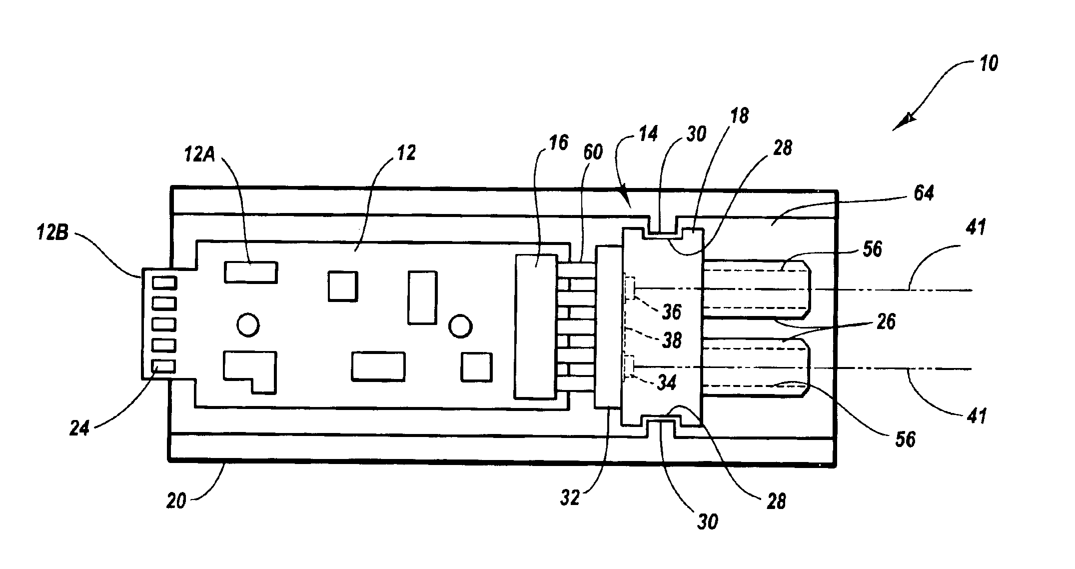
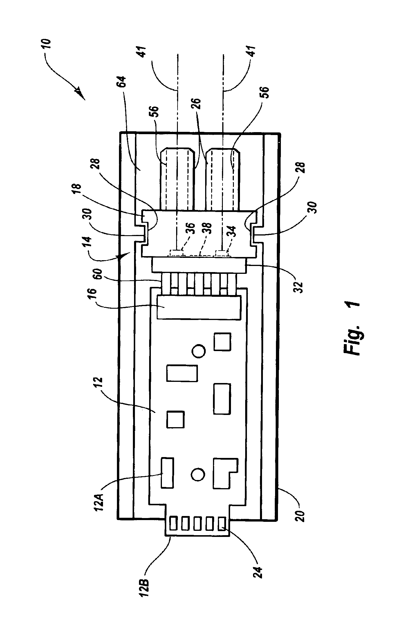
[0037]FIGS. 1-8 depict various features of embodiments of the present invention, which is generally directed to an optical transceiver for use in optical communications, the transceiver having simplified design and assembly characteristics. In particular, active optical components, such as the laser and the photodetector, are disposed together on a single printed circuit board within the transceiver body so as to enable a single alignment operation for the active components. The present transceiver also enables assembly thereof with a minimum of fasteners, speeding manufacture and reducing assembly costs. Finally, because of its design, the transcei...


PUM


Abstract

An optical transceiver module for use in optical communications networks is disclosed. The transceiver features a simplified optical subassembly structure that facilitates the alignment and calibration of active optical components located thereon. The transceiver includes a shell that contains a transceiver printed circuit board and a transmitter/receiver optical subassembly (“TROSA”) connected to the printed circuit board via a TROSA connector. The TROSA includes a singular substrate on which a laser for producing optical signals and a photodetector for receiving optical signals are disposed. The laser and photodetector are precisely positioned on the TROSA substrate to have a specified spacing therebetween. So positioned, the laser and photodetector can be aligned with conduits of a sleeve assembly in a single alignment operation, thereby simplifying calibration of the transceiver module. The present transceiver eliminates the use of multiple substrates separately supporting the laser and the photodetector, thus also eliminating related alignment challenges.

Description

BACKGROUND OF THE INVENTION[0001]1. The Field of the Invention[0002]The present invention is generally related to optical transceivers used in fiber optic communications systems. In particular, the present invention relates to an optical transceiver, and a method for making the same, wherein the transceiver comprises a simplified design that facilitates the more efficient manufacturing of such devices.[0003]2. The Related Technology[0004]Fiber optic technology is increasingly employed as a method by which information can be reliably transmitted via a communications network. Networks employing fiber optic technology are known as optical communications networks, and are marked by high bandwidth and reliable, high-speed data transmission.[0005]Optical communications networks employ optical transceivers in transmitting information via the network from a transmission node to a reception node. An optical transceiver at the transmission node receives an electrical signal from a network dev...

Claims


Application Information

Patent Timeline
IPC IPC(8): G02B6/42
CPCG02B6/42G02B6/4246G02B6/4292
Inventor ROSENBERG, PAUL K.SASSER, GARYTOGAMI, CHRISICE, DONALD A.
Owner II VI DELAWARE INC
Why Eureka
Try Eureka