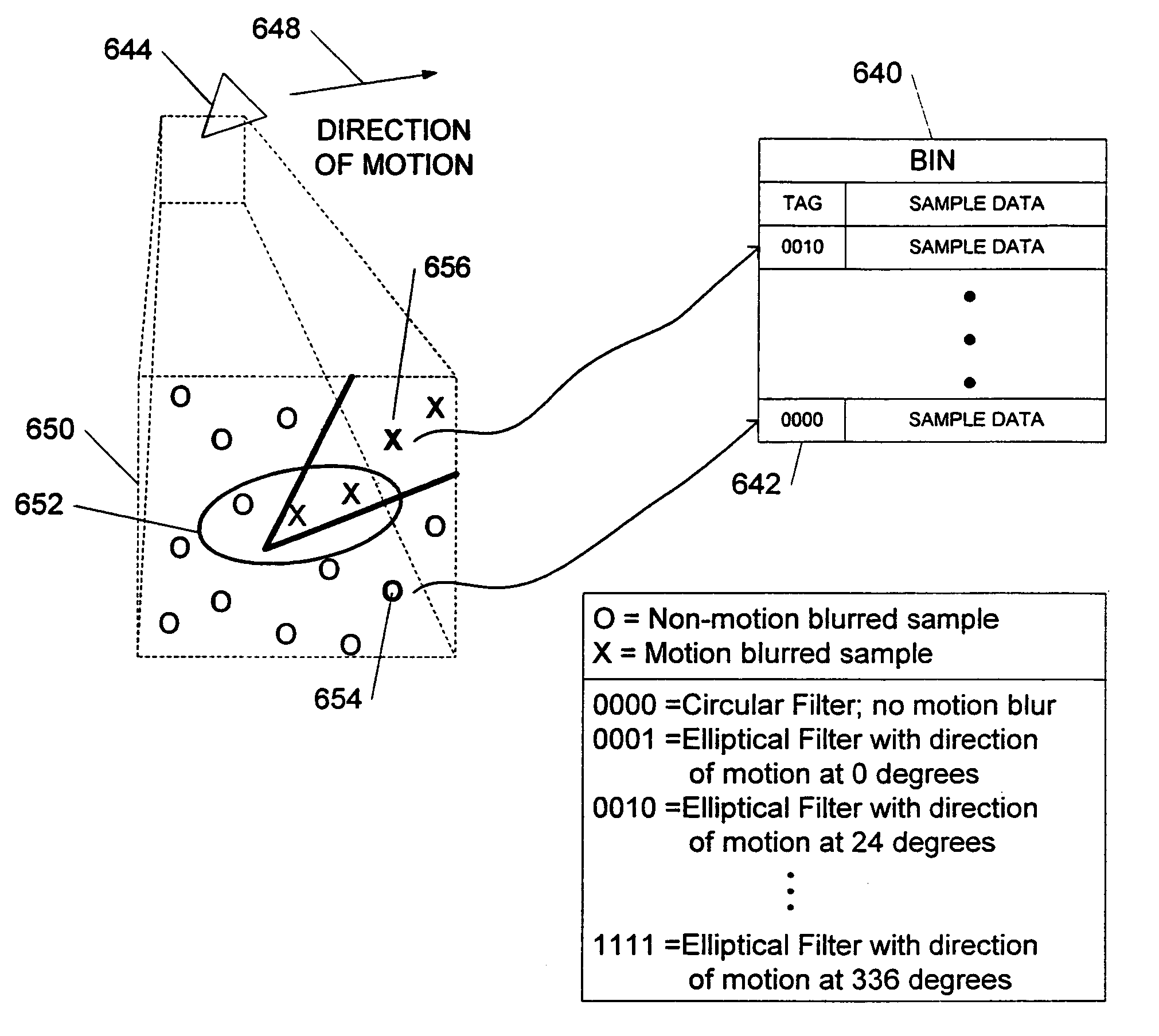
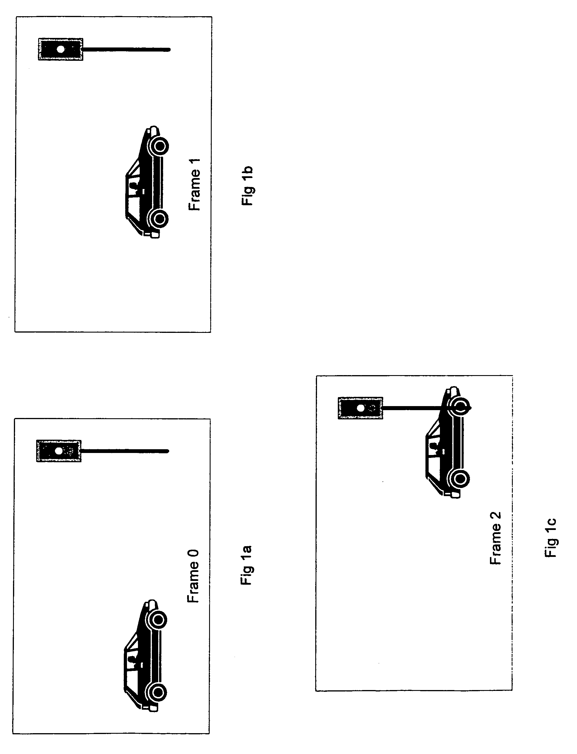
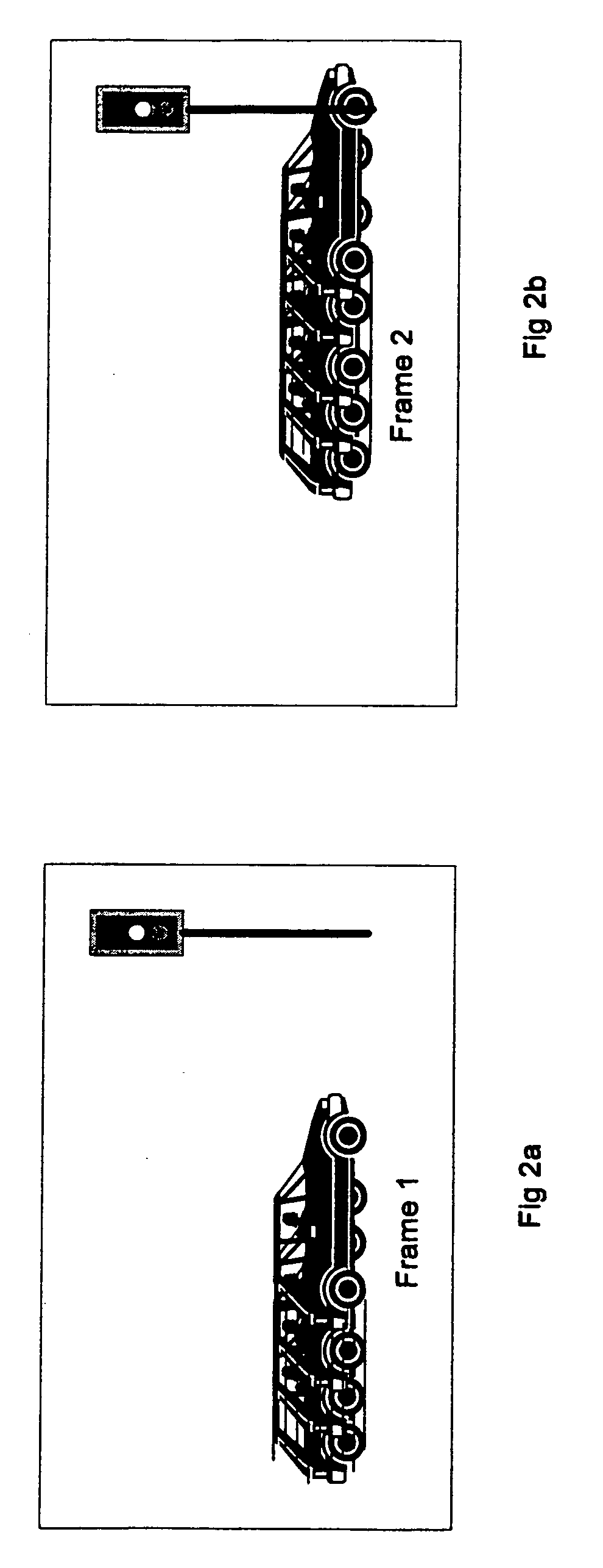
[0018]The present invention contemplates the use of a “super-sampled” graphics system that selectively renders samples into a sample buffer, and then, filters the samples in realtime to form output pixels. Advantageously, this configuration allows the graphics system to generate high quality images and to selectively apply one or more of the effects described above (i.e.,
motion blur,
depth of field, and screen door-type transparency) in real time.
[0023]In addition to, or in lieu of,
motion blur, the graphics system may be configured to perform transparency effects such as the “screen door” effect by selectively rendering samples for one or more objects into the sample buffer. For example, if an object is 50% transparent, a sample
mask may be used to
mask out one half of the samples that would normally have been rendered for the object. In this way, the object will only be “half there”. The newly rendered samples coexist with the older samples in the sample buffer and are filtered to create output pixels as in the embodiments described above. With eight times over-sampling, this method would provide nine levels of transparency. This method may allow transparency effects without a dedicated alpha channel.
[0029]The human
visual system has varying levels of acuity, with the highest level of acuity occurring in the vicinity of the foveal pit of the
retina. The foveal region receives light from the point of foveation and typically accounts for only a few degrees at the center of a human's of field of vision. Thus, to best match the human
visual system, the graphics system may, in some embodiments, be configured to detect where the viewer's point of foveation is relative to the display device. This allows the graphics system to match the sample density to the
human eye's acuity. Thus, more samples (and more processing power) will be allocated to areas of the display device that will be perceived by the highest acuity regions of the human
visual system. Similarly, less samples and processing power will be devoted to regions that will be perceived by the lower acuity regions of the human visual system. Note however, it is not just the density of rods and cones in the eye that may be matched. Other factors also influence the
perception of the human visual system, including the lens system, chromatic aberrations, and the neural pathways to the eye. For the purposes of matching computer displays to human
retinal perception, the
human brain's processing limits for visual input provides a useful target that future graphics systems may strive to match or exceed.
[0030]This type of graphics system may be implemented in a number of different ways. For example, eye-tracking sensors may be used to determine in what direction the viewer's eyes are directed. This may provide data with which to predict where the viewer's point of foveation is. Typically, head-mounted eye-tracking sensors may use an additional head-tracking sensor. Taken together, the eye- and head-tracking sensors can provide useful information about the position and movement of a viewer's point of foveation relative to the display device. Even further accuracy may be obtained using two eye-tracking sensors (i.e., one for each of the viewer's eyes). Thus two points of foveation may be detected for each viewer. Furthermore, in some configurations multiple viewers may each have their points of foveation detected. Other configurations may utilize a hand-tracking sensor (e.g., pointing wand or data glove) in combination with head- and or eye-tracking sensors. Another configuration may utilize a head-mounted display with various motion, direction, eye-tracking and or head-tracking sensors. A higher number of samples may be allocated to a region of a predetermined size centered at the calculated point of foveation to compensate for inaccuracies in the sensors (i.e., to ensure that the actual point of foveation will receive pixels generated from a high sample density). Note as used herein, the term “
gaze tracking unit” refers to any combination of eye-tracking, head-tracking, hand tracking, and or body tracking sensors that provide information concerning one or more viewers' points of foveation (there can be two points of foveation for each viewer). Examples of
gaze tracking units may include one or more of the following: video cameras, electromyograph sensors that detect electrical currents in
eye muscles, an eye-and-head tracker, an eye tracker, a head tracker, a hand tracker, a data glove, a wand, a data suit, a mouse, a
body position sensor, a
body position sensing chair,
motion sensors, pressure sensors, acoustic sensors, and infra-red scanners / sensors. In other embodiments, the system may assume that the viewer's point of foveation is located at a fixed location near the center of the screen, or at a varying point of interest on the display created by the
software application being executed.

