Automated fabrication of an integral fiber reinforced composite structural component using a positioning and assembly support

a technology of positioning and assembly support and composite structural components, which is applied in the direction of process and machine control, mechanical control devices, instruments, etc., can solve the problems of increasing the rejection rate, affecting the quality of the product, and each manual step in the process suffers a significant risk of inaccurate or inconsistent positioning and positioning of several elements, etc., to achieve accurate positioning and forming, accurate automated positioning and placement of stringers

Active Publication Date: 2005-10-25
AIRBUS OPERATIONS GMBH
View PDF5 Cites 19 Cited by
  • Summary
  • Abstract
  • Description
  • Claims
  • Application Information

AI Technical Summary

Benefits of technology

[0007]Through the use of the positioning and assembly support according to the invention, having defined reference contours facing toward and cooperating with a molding tool, the invention advantageously ensures that all of the structural elements being used to fabricate the structural component are necessarily precisely positioned and then fixed in defined positions in a positively enforced manner. Thereby, an automated locating of the structural elements in a structural shell is advantageously achieved.
[0018]An advantage of the inventive method is achieved by the uniform and substantially tension-free pre-forming of the vacuum film in a defined reference position on the outer forming surface of the forming jig, such that a vacuum can be pre-established, and then the actual vacuum skin of the component to be fabricated can be applied in a form-fitting manner onto the outer forming surface of the forming jig while simultaneously removing the temporary film, and thereby maintaining the vacuum. This achieves an accurate positioning and forming of the vacuum skin on the forming surface and in the sectional grooves of the jig, which further enables the accurate automated positioning and placement of the stringers in the grooves relative to the structural shell, and also enables an automatic sealing of the accurately positioned structural elements in a fully automated or substantially automated process.

Problems solved by technology

With such a vacuum bag fabrication method, considerable quality risks arise, especially in connection with the fabrication of integrally stiffened structures such as fuselage shell structures, due to the manual positioning of the individual structural elements and the manual application of a vacuum skin as well as the manual sealing thereof.
Each manual step in the process suffers a significant risk of inaccurate or inconsistent positioning and arranging of the several elements.
That results in an increased reject rate, reduced strength, and / or increased tolerance variations of the finished structural components.
An automated fabrication of structural components using such a vacuum bag technique is not possible.

Method used


Image

  • Automated fabrication of an integral fiber reinforced composite structural component using a positioning and assembly support
  • Automated fabrication of an integral fiber reinforced composite structural component using a positioning and assembly support
  • Automated fabrication of an integral fiber reinforced composite structural component using a positioning and assembly support

Examples


Embodiment Construction

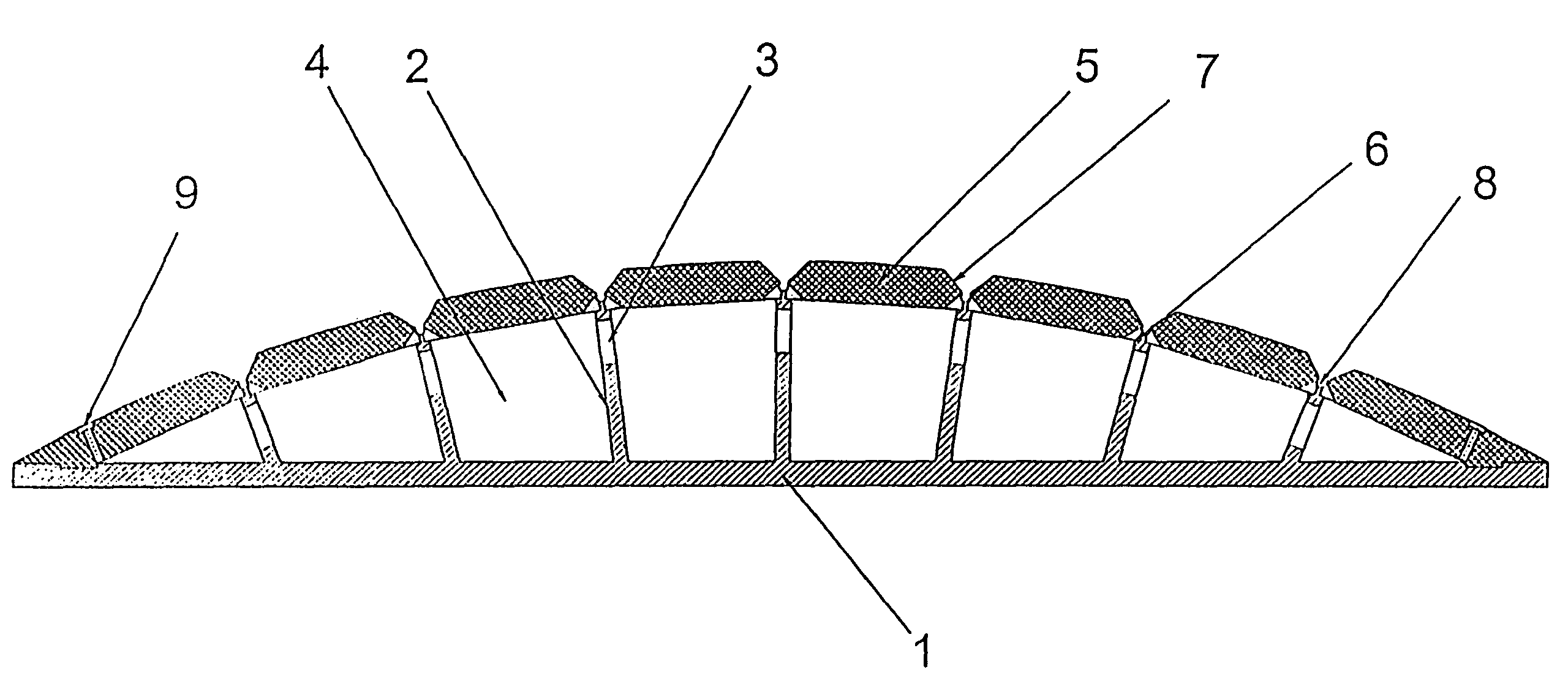
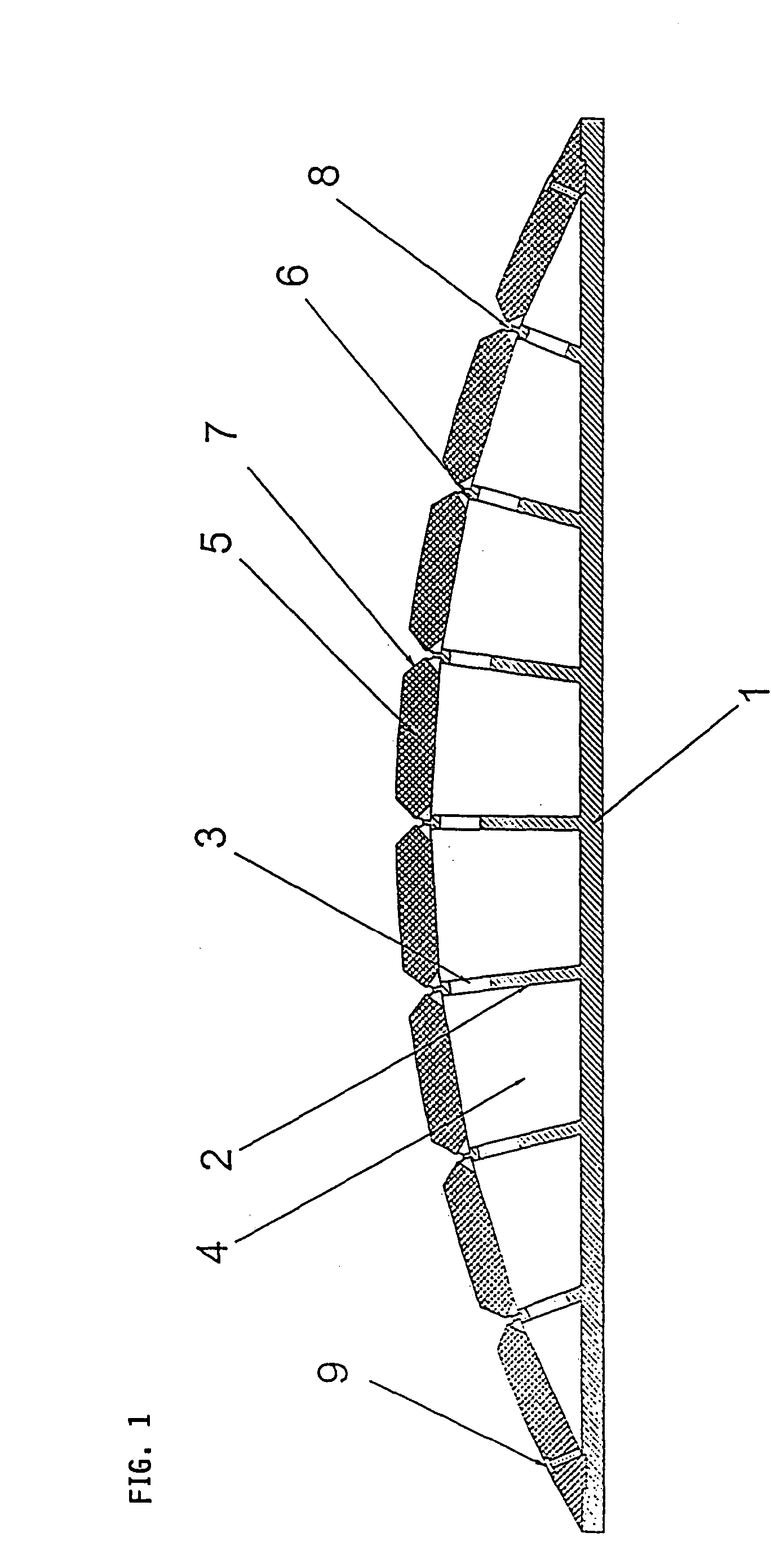
[0029]The forming jig or positioning and assembly support shown in FIG. 1 includes a flat planar and elongated support base 1 that is solid and vacuum-tight all the way out to its lateral edges. A plurality of supporting walls 2 (e.g. in the present example seven supporting walls 2) of respective different lengths or protruding heights from the support base 1 are arranged and secured on the support base 1 so as to protrude generally upwardly therefrom while forming a grid of the walls 2 on the base 1. The support base 1 and the support walls 2 are preferably made of metal, for example a light metal or metal alloy, and the support walls 2 may be welded onto the support base 1, for example. The upper free ends of the support walls 2 all lie on a curved or arcuate imaginary surface that generally corresponds to the curvature of the structural component that is to be fabricated. The respective support walls 2 each protrude respectively at a different angle from the support base 1, where...


PUM

PropertyMeasurementUnit
vacuumaaaaaaaaaa
perimeteraaaaaaaaaa
vacuum levelaaaaaaaaaa

Abstract

A forming jig includes a grid pattern of support walls arranged on a support base and having upper free ends located along an imaginary curved surface, and modular sectional profile members arranged on the walls to enclose a vacuum chamber within the jig. Grooves, channels and air passages between neighboring profile members communicate into the vacuum chamber. The outer surface of the profile members matches the intended inner surface of a structural component to be fabricated using the jig. In the fabrication process, a film is applied to the outer surface to pre-establish a vacuum, the film is removed while simultaneously a vacuum skin is applied, stringer members are set into the grooves, fiber skin layers are laid up, a sealant is applied around the perimeter, a structural shell is vacuumed onto the skin layers, and then this preformed component is removed from the jig, injected with resin unless the skin layers were pre-impregnated with resin, and cured.

Description

PRIORITY CLAIM[0001]This application is based on and claims the priority under 35 U.S.C. §119 of German Patent Applications 102 36 546.6, filed on Aug. 8, 2002 and 103 31 358.3, filed on Jul. 11, 2003, the entire disclosures of which are incorporated herein by reference.FIELD OF THE INVENTION[0002]The invention relates to an apparatus or system including a positioning and assembling or fabricating support (or so-called forming jig), as well as a method for carrying out the automated fabrication of an integral structural component made of a fiber reinforced composite material for high performance or high strength applications, for example preferably a structural shell strengthened with stringers arranged at prescribed spacing distances, for use in the construction of an aircraft fuselage.BACKGROUND INFORMATION[0003]High performance and high strength fiber reinforced composite materials are predominantly processed by means of a vacuum bag method for fabricating various lightweight str...

Claims


Application Information

Patent Timeline
Patent Type & Authority Patents(United States)
IPC IPC(8): B29C70/04B29C70/00B29C70/86B29C70/44B29C70/48
CPCB29C70/443B29C70/865B29C70/48Y02T50/433Y02T50/40
Inventor HERRMANN, AXEL SIEGFRIEDPABSCH, ARNO
Owner AIRBUS OPERATIONS GMBH
Why Eureka
Try Eureka