Phased array metamaterial antenna system

a phased array and metamaterial technology, applied in the direction of antennas, antenna details, waveguides, etc., can solve the problems of high signal attenuation, limited improvement of antenna systems in certain regards, and inability to meet the requirements of lithographically printed microstrip transmission lines, so as to achieve the effect of improving the size and cost of in-vehicle phased array antenna systems, poor sidelobe performance, and high signal attenuation

Active Publication Date: 2005-10-25
LUCENT TECH INC
View PDF3 Cites 362 Cited by
  • Summary
  • Abstract
  • Description
  • Claims
  • Application Information

AI Technical Summary

Benefits of technology

[0005]The present inventor has realized that, while the size and cost of in-vehicle phased array antenna systems has improved, due in part to the lithographic processes used to manufacture modern antenna systems, even the improved antenna systems are limited in certain regards. For example, recent attempts of implementing in-vehicle radar have focused on the 76–77 GHz frequency range and recent data communications attempts have been made in the 71–76 GHz and the 81–86 GHz frequency range. However, at such frequencies, antenna systems with lithographically-printed microstrip transmission lines experience a high degree of signal attenuation. Additionally, such printed antenna systems have relied on a signal-feed / delay line architecture that resulted in a biconvex, or Fresnel, lens for focusing the microwaves. The use of such lens architectures resulted in microwave radiation patterns having poor sidelobe performance due to signal attenuation of electromagnetic energy as it passed through the lens. Specifically, the signal passing through the center portion of the lens was attenuated to a greater degree than the signal passing through the edges of the lens, thus resulting in significant sidelobes. While signal delay lines in the lens portion of the system could reduce the sidelobes and, as a result, increase the amplitude performance of the phased array system, this was also limited in its usefulness because, by implementing such delay lines, the operating bandwidth of the phased-array system was reduced.
[0006]Therefore, the present inventor has invented an efficient, low-loss, low sidelobe, high dynamic range phased-array radar antenna system that essentially solves the aforementioned problems. In one embodiment, the present invention uses metamaterials, which are manmade composite materials having a negative index of refraction, to create a biconcave lens architecture (instead of the aforementioned biconvex lens) for focusing the microwaves transmitted by the antenna. Accordingly, a signal passing through the center of the lens is attenuated to a lesser degree relative to the edges of the lens, thus significantly reducing the amplitude of the sidelobes of the antenna while, at the same time, retaining a relatively wide useful bandwidth.
[0007]In another embodiment, attenuation across microstrip transmission lines is reduced by using low loss transmission lines that are suspended above a ground plane a predetermined distance in a way such they are not in contact with a solid substrate. By suspending the microstrip transmission lines in this manner, dielectric signal loss is reduced significantly, thus resulting in a less-attenuated signal at its destination.

Problems solved by technology

The present inventor has realized that, while the size and cost of in-vehicle phased array antenna systems has improved, due in part to the lithographic processes used to manufacture modern antenna systems, even the improved antenna systems are limited in certain regards.
However, at such frequencies, antenna systems with lithographically-printed microstrip transmission lines experience a high degree of signal attenuation.
The use of such lens architectures resulted in microwave radiation patterns having poor sidelobe performance due to signal attenuation of electromagnetic energy as it passed through the lens.
Specifically, the signal passing through the center portion of the lens was attenuated to a greater degree than the signal passing through the edges of the lens, thus resulting in significant sidelobes.
While signal delay lines in the lens portion of the system could reduce the sidelobes and, as a result, increase the amplitude performance of the phased array system, this was also limited in its usefulness because, by implementing such delay lines, the operating bandwidth of the phased-array system was reduced.

Method used


Image

  • Phased array metamaterial antenna system
  • Phased array metamaterial antenna system
  • Phased array metamaterial antenna system

Examples


Embodiment Construction

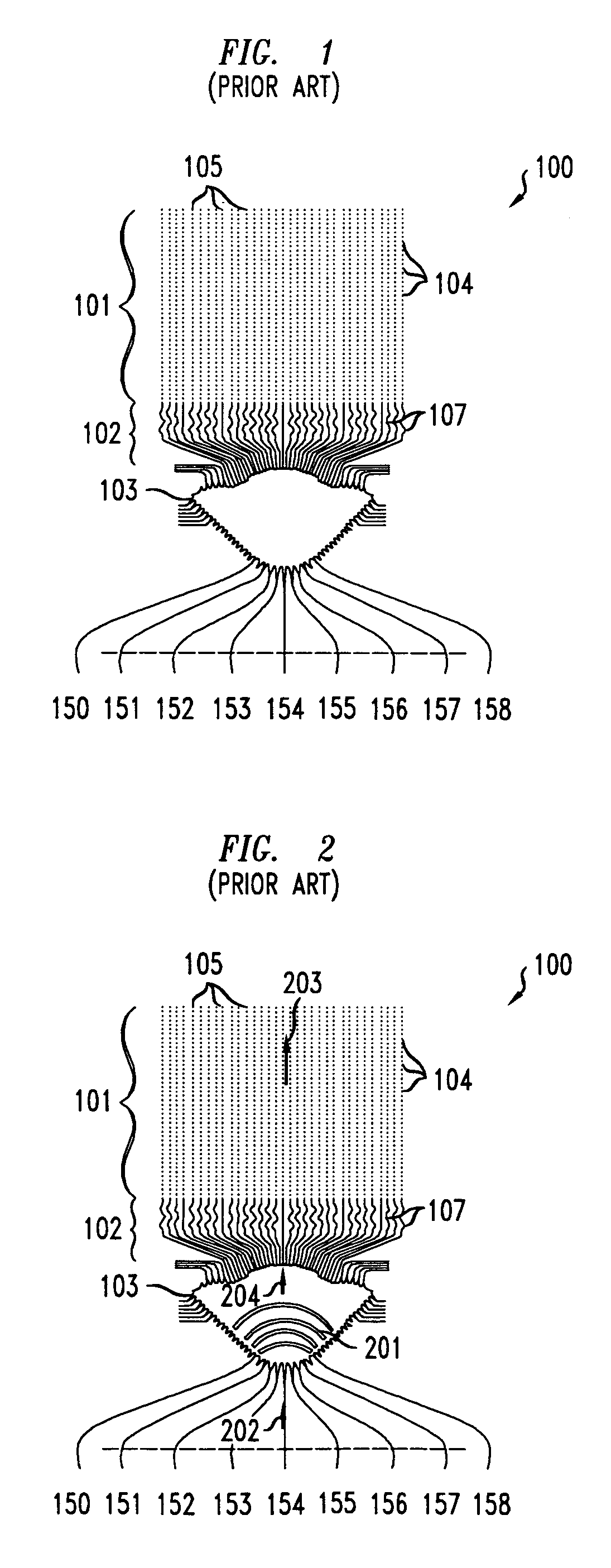
[0013]FIG. 1 shows one illustrative, relatively low-cost prior art antenna system potentially useful for telecommunications and in-vehicle radar uses. Specifically, FIG. 1 shows a monolithic microwave integrated circuit (MMIC) phased array antenna system 100 which has antenna 101, lens portion 102, waveguide 103 and signal input lines 150–158. Antenna 101 has an array of antenna elements 101 wherein the individual elements 104 of each column 105 are electrically connected to each other. The individual columns 105 are, for example, lithographically printed microstrip lines with printed antenna patches disposed periodically along the microstrip lines. Each column 105 of antenna elements 104 is connected to one of delay lines 107 which are suitable for use as waveguides for electromagnetic signals. Delay lines 107 are, for example, microstrip lines lithographically printed on a suitable substrate. One or more electronic components, such as amplifiers, may be disposed along each of the ...


PUM


Abstract

An efficient, low-loss, low sidelobe, high dynamic range phased-array radar antenna system is disclosed that uses metamaterials, which are manmade composite materials having a negative index of refraction, to create a biconcave lens architecture (instead of the aforementioned biconvex lens) for focusing the microwaves transmitted by the antenna. Accordingly, the sidelobes of the antenna are reduced. Attenuation across microstrip transmission lines may be reduced by using low loss transmission lines that are suspended above a ground plane a predetermined distance in a way such they are not in contact with a solid substrate. By suspending the microstrip transmission lines in this manner, dielectric signal loss is reduced significantly, thus resulting in a less-attenuated signal at its destination.

Description

CROSS-REFERENCE TO RELATED APPLICATIONS[0001]This application claims priority to U.S. Provisional Patent Application, Ser. No. 60 / 550,473, entitled Phased Array Metamaterial Antenna System, filed Mar. 5, 2004.FIELD OF THE INVENTION[0002]The present invention relates to phased array antenna systems and, more particularly, to phased array antenna systems useful in automotive radar applications.BACKGROUND OF THE INVENTION[0003]Phased array systems and antennas for use in such systems are well known in, for example, telecommunications and radar applications. Such systems generally employ fixed, planar arrays of individual transmit and receive elements. When receiving electromagnetic (EM) signals, such as a communication signal or the return signal in a radar system, phased array systems receive signals at the individual elements and coherently reassemble the signals over the entire array by compensating for the relative phases and time delays between the elements. When transmitting sign...

Claims


Application Information

Patent Timeline
Patent Type & Authority Patents(United States)
IPC IPC(8): H01Q19/06H01Q1/38H01Q19/00H01Q3/26
CPCH01P3/08H01P3/081H01Q3/26
Inventor METZ, CARSTEN
Owner LUCENT TECH INC
Why Eureka
Try Eureka