
Liquid crystal display device

a liquid crystal display and display screen technology, applied in static indicating devices, instruments, non-linear optics, etc., can solve the problems of reducing the yield rate of the liquid crystal display device, reducing the driving capability of each pixel, and difficult to secure a sufficient tolerance for device characteristics dispersion, so as to avoid point defects on the display screen and insufficient driving capability of the memory

Inactive Publication Date: 2005-10-25
KK TOSHIBA
View PDF5 Cites 26 Cited by
  • Summary
  • Abstract
  • Description
  • Claims
  • Application Information

AI Technical Summary

Benefits of technology

[0004]The present invention provides a liquid crystal display device configured to reduce such point defects caused by the driving capability of a digital memory.
[0006]In this liquid crystal display device, as set forth above, the separation circuits make the auxiliary capacitor lines separate from the potential setting terminals and keep the potential setting terminals in an electrically floating state during a period of time when the connection control circuits connect the memories to the pixels. As a result, since the auxiliary capacitor lines and auxiliary capacitors between the pixel electrodes are removed from capacitive loads to and from which the memories charge and discharge the video signal, respectively, the memories can correctly drive the pixels in response to the video signal even where the driving capability of the memories are lower than their designed values due to the dispersion of device characteristics based on the device production process. Thus, the liquid crystal display device can substantially avoid point defects on the display screen possibly caused by the insufficient driving capability of the memories.

Problems solved by technology

In this liquid crystal display device, where an area per pixel is made small to achieve high definition display, the digital memory provided for each pixel is necessarily so small in size that the digital memory restricts the driving capability of each pixel.
In the case of such a restriction, it is quite difficult to secure a sufficient tolerance for dispersion of device characteristics depending on the device production process.
Where the driving capability of a digital memory is lower than its designed values with respect to an electric capacitor of a liquid crystal and its auxiliary capacitor, a point defect takes place at a pixel mistakenly driven by that digital memory in the still picture display mode.
This results in a lower yield rate of the liquid crystal display device.

Method used


Image

  • Liquid crystal display device
  • Liquid crystal display device
  • Liquid crystal display device

Examples


Embodiment Construction

[0017]Embodiments of an active matrix type liquid crystal display device in accordance with the present invention will be explained below with reference to the attached figures, in which like reference numerals indicate identical or corresponding elements throughout the figures. The active matrix display device is applicable to monitor displays of compact information processing terminals that are enabled to operate in an ordinary display mode of moving pictures and in a still picture display mode as well.

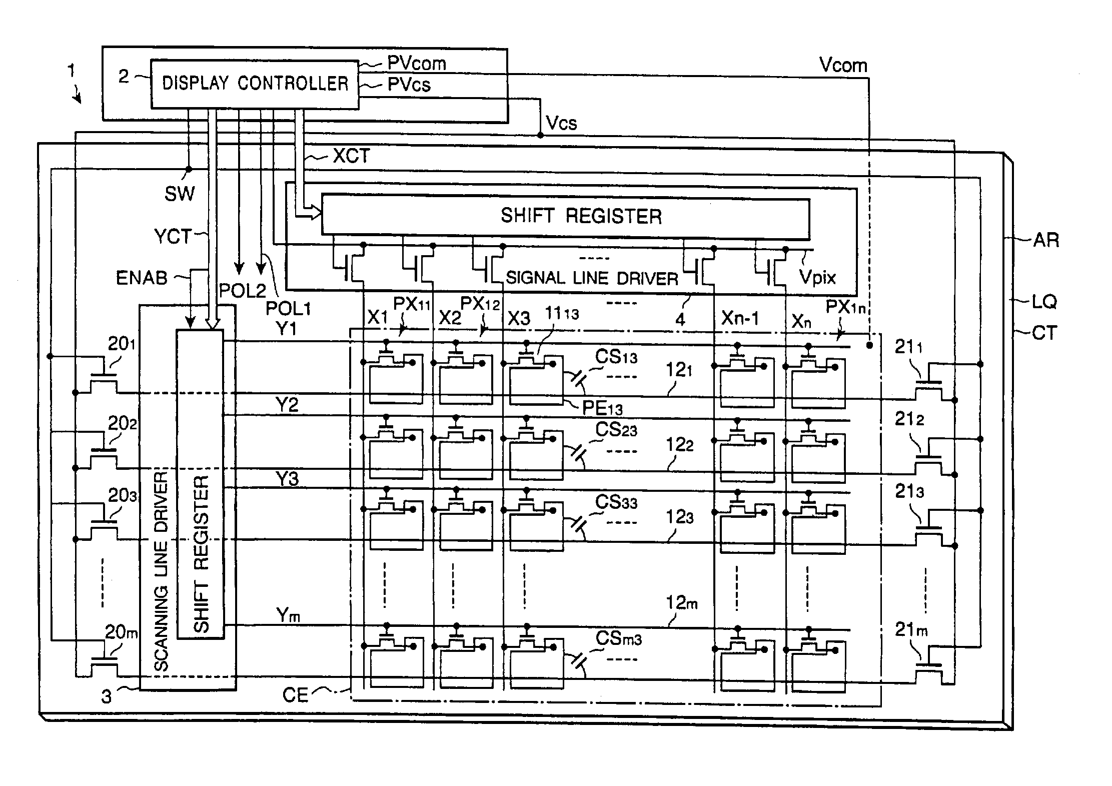
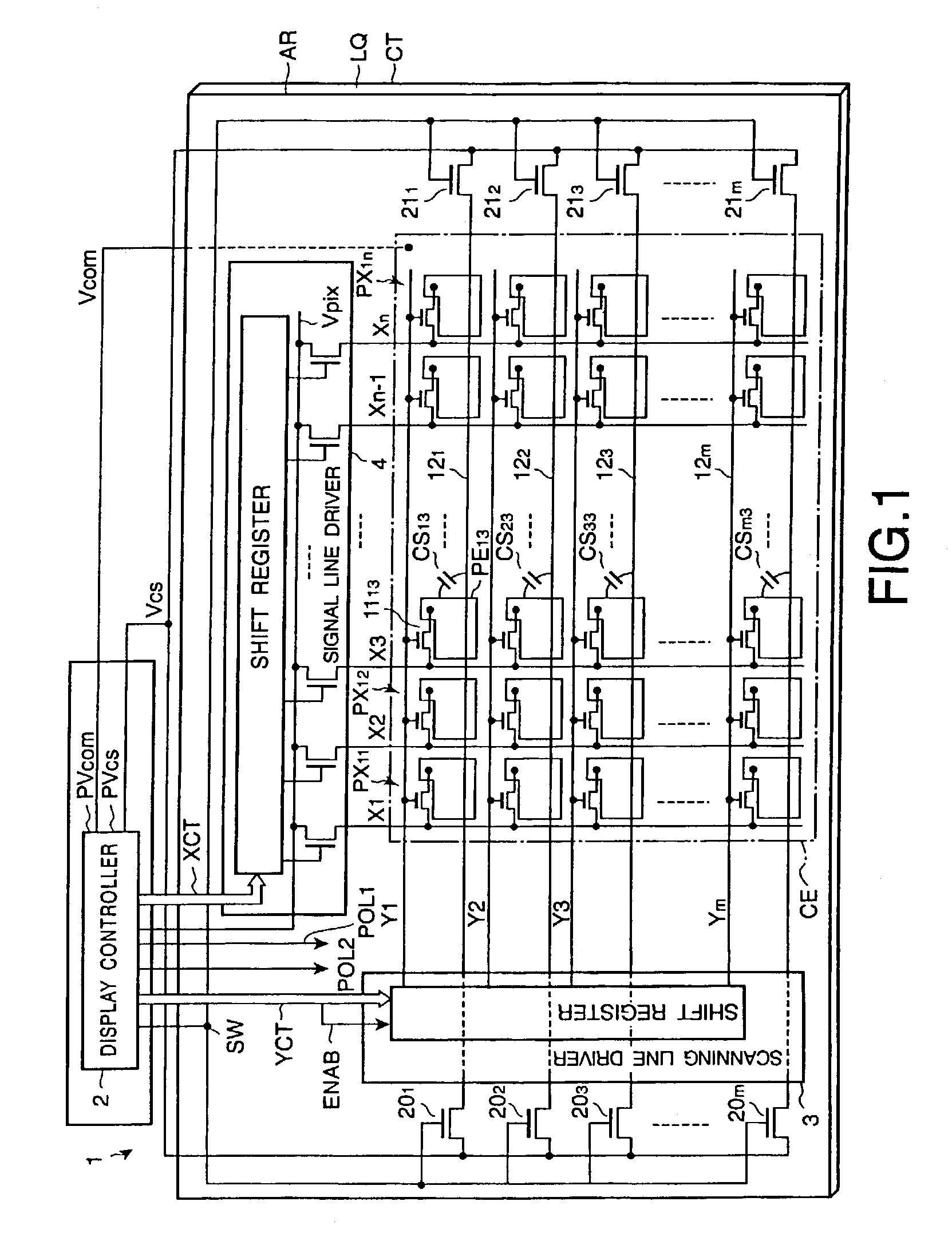
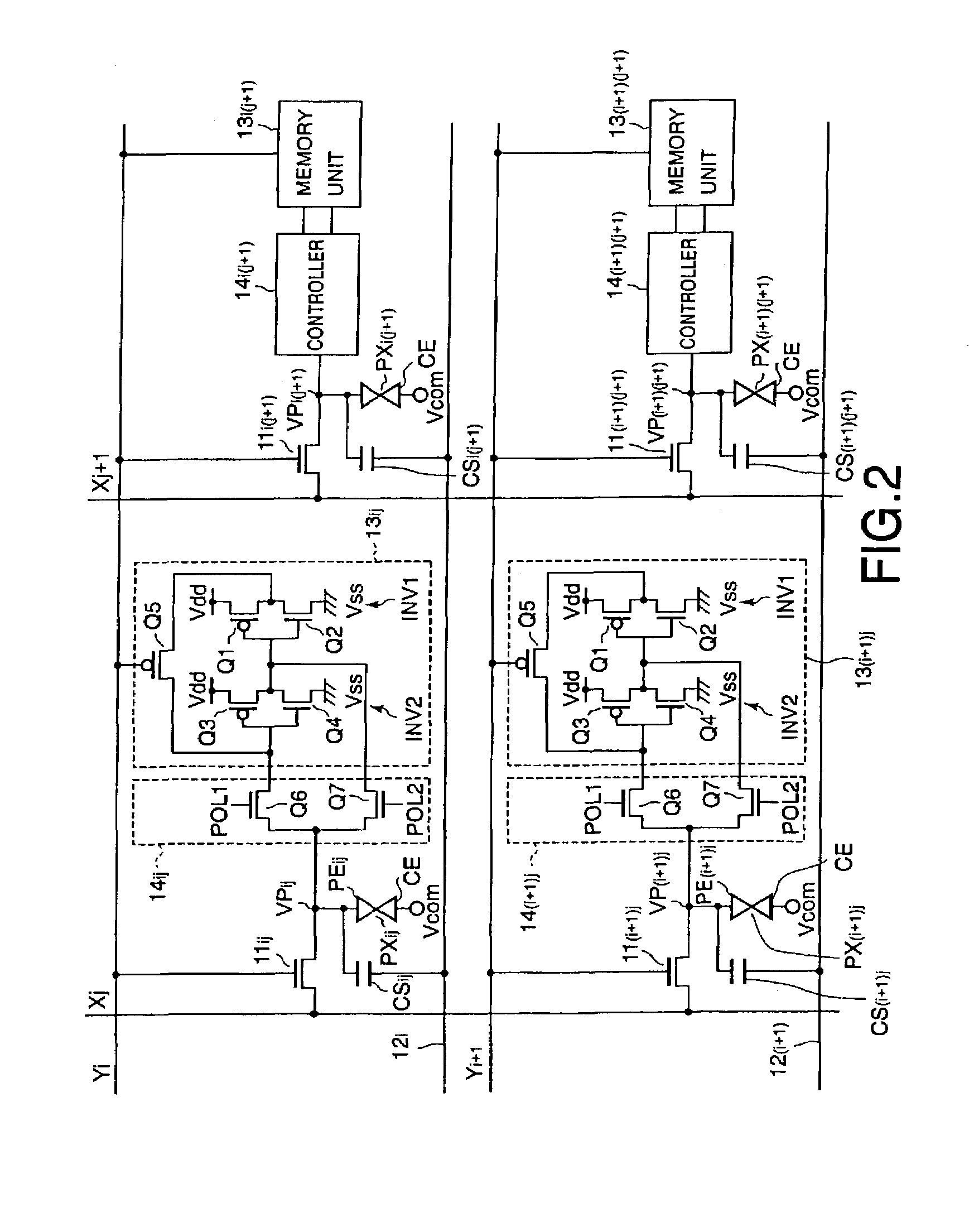
[0018]FIG. 1 shows a schematic plan view of the structure of such an active matrix type liquid crystal display device and FIG. 2 shows equivalent circuits of the pixels and their peripheral components in the liquid crystal display device shown in FIG. 1.

[0019]As shown in FIG. 1, the liquid crystal display device includes a display panel 1 and a display controller 2 to control the display panel 1. The display panel 1 is provided with a liquid crystal layer LQ, as an optical modulator...


PUM

PropertyMeasurementUnit
voltagesaaaaaaaaaa
polaritiesaaaaaaaaaa
polarityaaaaaaaaaa

Abstract

A liquid crystal display device includes pixels having pixel electrodes and a common electrode. A liquid crystal material is held between the pixel electrodes and common electrode. Pixel switches are provided to supply video signals to the pixel electrodes. A plurality of memories are provided to store the video signals in a digital form supplied from the switches to the pixel electrodes. Connection controllers connect the memories to the pixel electrodes and periodically reverse polarities of the video signals output from the memories to the pixel electrodes with respect to potential of the common electrode. A potential setting terminal is provided and auxiliary capacitor lines connected to the potential setting terminal constitute capacitive coupling with the pixel electrodes. Separation circuits are provided to keep the auxiliary capacitor lines in an electrically floating state by electrically disconnecting the auxiliary capacitor lines from the potential setting terminal while the connection controllers connect the memories to the pixels.

Description

FIELD OF THE INVENTION[0001]This invention generally relates to a liquid crystal display device driven by video signals derived from regularly reversing the polarity of pixel signals and, more particularly, to a liquid crystal display device with memories for holding such video signals in digital form and supplying the video signals to pixel electrodes.BACKGROUND OF THE INVENTION[0002]Liquid crystal display (LED) devices have the advantages of being light weight, thin, and consuming low power, and as a result LCDs have been used for display devices for compact information processing terminals, such as mobile phones, electric dictionaries, etc. Since those compact information processing terminals are usually driven by batteries, it is quite important to reduce power consumption from a view point of making their operation time longer. In the case of a mobile phone, for instance, its power consumption must be as little as possible, at least in the standby state. As a method to comply w...

Claims


Application Information

Patent Timeline
Patent Type & Authority Patents(United States)
IPC IPC(8): G02F1/133G02F1/13G09G3/20G09G3/36
CPCG09G3/3614G09G3/3648G09G3/3655G09G2300/0809G09G2300/0842G09G2300/0857G09G2300/0876G09G3/36
Inventor NAKAMURA, NORIO
Owner KK TOSHIBA
Learn More