Image sensing apparatus and image processing method therefor

a technology image processing method, which is applied in the field of image sensing apparatus, can solve the problems of inability to exchange lenses, increase the size of the camera body, and decrease the spatial frequency of an image, so as to reduce pseudo colors without increasing the size or cost of the image sensing apparatus, and reduce the effect of pseudo colors

Inactive Publication Date: 2005-10-25
CANON KK
View PDF32 Cites 57 Cited by
  • Summary
  • Abstract
  • Description
  • Claims
  • Application Information

AI Technical Summary

Benefits of technology

[0012]Furthermore, another object of the present invention is to provide an image sensing apparatus which can reduce pseudo colors without increasing the size or cost of the image sensing apparatus, and an image processing method for the image sensing apparatus.
[0013]Furthermore, another object of the present invention is to provide an image sensing apparatus which can reduce pseudo colors with relatively a simple construction, and an image processing method for the image sensing apparatus.
[0014]Furthermore, Another object of the present invention is to provide an image sensing apparatus which can reduce pseudo colors in isolated pixels with relatively a simple construction, and an image processing method for the image sensing apparatus.
[0026]Herein, the pseudo color removing step comprises: a determination step of determining whether or not the high frequency component of the luminance data and the hue data fall within a color range of the pseudo color; and a step of reducing a value of the color difference data, determined to be within the color range in said determination step.

Problems solved by technology

A conventional single-plate color digital camera is a lens-integrated system, and is generally incapable of exchanging a lens.
However, securing space for an optical low pass filter before a CCD causes to increase the size of the camera body.
Furthermore, although such optical low pass filter can reduce moiré or pseudo colors to a certain degree, a problem arises in that spatial frequency of an image decreases, and as a result, the image loses exact-focused characteristic such as that obtained in silver chloride photographs.
However, since the order of the digital filter is limited, original image data resolution cannot be sufficiently expressed.
This technique is effective to reduce pseudo colors, but not effective for moiré.
Even with the conventional technique, isolated pseudo colors, generated particularly around small characters or the like, cannot completely be eliminated.
However, even if such conventional technique is employed, pseudo colors in color interpolation cannot completely be eliminated.
However, in the case of checker flag patterns shown in FIGS. 21 and 22, a low frequency image of green cannot be distinguished from that of magenta, making it impossible to determine pseudo colors.
As a result, although the level of pseudo colors is reduced, the pseudo color components are spread out to the peripheral pixels, causing problems.
Furthermore, if the image data is compressed according to JPEG or the like without performing above-described pseudo color removing processing, block noise or the like may be caused.
Moreover, if the frequency band of color difference is forcefully limited for JPEG compression, an image becomes blurred.
As a result, although the level of pseudo colors is reduced, the pseudo color components are spread out to the peripheral pixels, causing problems.
However, such construction increases the size and cost of the camera.

Method used


Image

  • Image sensing apparatus and image processing method therefor
  • Image sensing apparatus and image processing method therefor
  • Image sensing apparatus and image processing method therefor

Examples


first embodiment

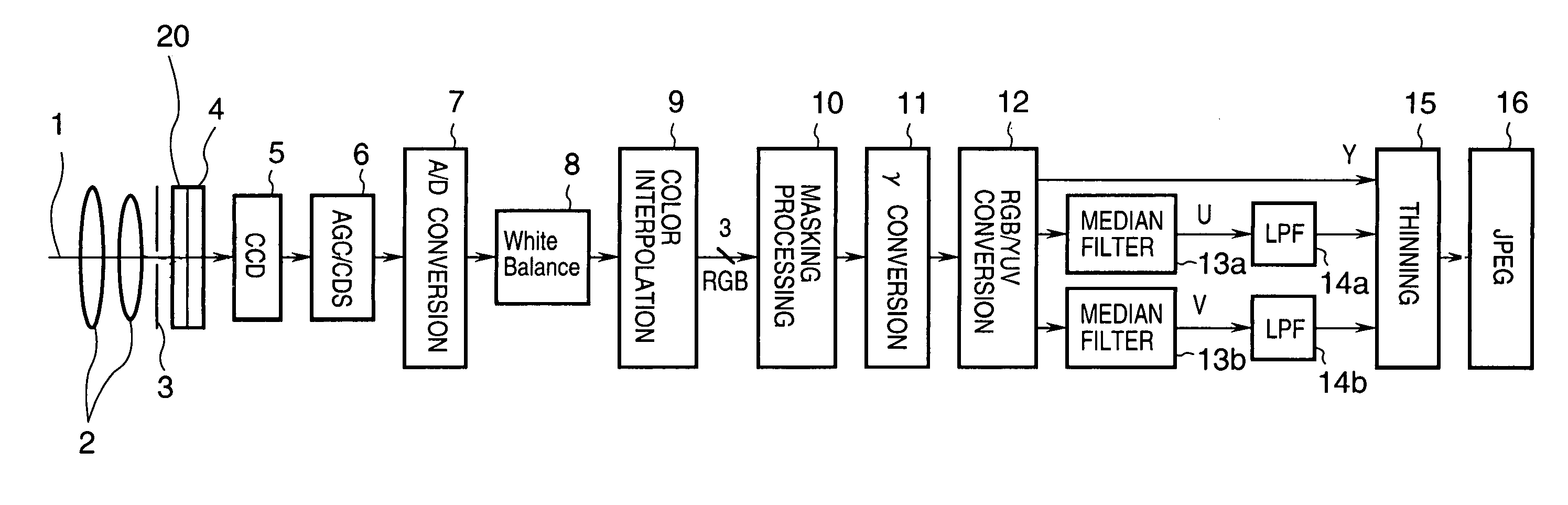
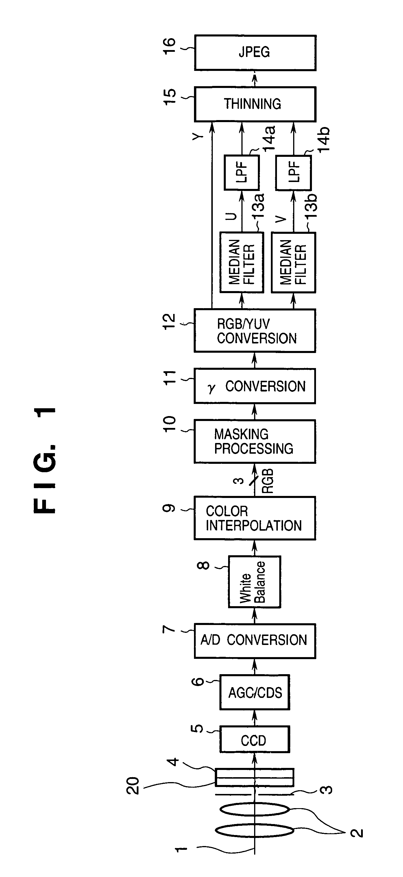
[0055]FIG. 1 is a block diagram showing, mainly, a construction of an image processing unit of a digital camera according to a first embodiment of the present invention.

[0056]Light 1, incident upon the digital camera according to the first embodiment, passes through lens 2, then the amount of the light is adjusted by a diaphragm 3, and an image sensing device 5 (hereinafter referred to as a CCD), e.g., CCD or CMOS, is exposed while a shutter (not shown) is open. Before the light 1 is incident upon the CCD 5, an optical low pass filter 20 limits a spatial frequency of the light 1 to reduce moiré in a way that an optical area of a long wavelength is cut off by an infrared ray (IR) filter 4 so that the CCD 5 does not detect light in the infrared region. By the light incident upon the CCD 5, the amount of electric charge corresponding to the intensity of light is accumulated in the CCD 5. The amount of electric charge is amplified by a predetermined gain by a CDS-AGC 6, and converted to...

second embodiment

[0063]In the above-described first embodiment, color conversion from RGB to YUV color space is performed and pseudo color reduction processing is performed in the YUV color space before image compression is performed according to JPEG or the like. However, pseudo color reduction processing is not necessarily performed in YUV color space, but may be performed in another color space.

[0064]According to the second embodiment of the present invention, pseudo color removal is performed by a median filter, after a color space of input image data is converted from RGB color space to Y, R-Y, B-Y color space.

[0065]FIG. 3 is a block diagram showing a construction of an image processing unit of a digital camera according to the second embodiment. For the components that are common to the construction shown in FIG. 1, the same reference numerals are assigned and description thereof will be omitted. The second embodiment largely differs from the foregoing first embodiment in that the second embod...

third embodiment

[0070]In the above-described second embodiment, the luminance signal Y is consciously calculated from R, G and B signals. However, in image processing, G signal of the R, G and B may substitute for the luminance signal Y.

[0071]The third embodiment is characterized by employing G, R-G and B-G signals instead of Y, R-Y and B-Y signals employed in the second embodiment, and executing median filtering to R-G and B-G signals respectively.

[0072]FIG. 4 is a block diagram showing a construction of an image processing unit of a digital camera according to the third embodiment of the present invention. For the components that are common to the construction shown in FIG. 3, the same reference numerals are assigned and description thereof will be omitted.

[0073]According to the third embodiment, the amount of calculation is reduced further when compared against the case of converting R, G and B signals to luminance signal Y and color difference signals R-Y and B-Y. The G, R-G, B-G converter 18a ...


PUM

PropertyMeasurementUnit
color spaceaaaaaaaaaa
coloraaaaaaaaaa
color interpolationaaaaaaaaaa

Abstract

An image sensing apparatus comprising: a CCD, optical system for forming an image on the CCD; A / D converter for converting an image signal outputted by the CCD to a digital signal; color interpolator for performing color interpolation on the digital signal converted by the A / D converter and generating image data on R, G and B color planes; color space converter for converting RGB color space to YUV colorimetric system; and median filter for reducing pseudo color components, generated by the color interpolator, by controlling color difference signals U and V. By cutting high frequency components of the signal, filtered by the median filter, then thinning out YUV signals and performing JPEG compression, pseudo color components generated by color interpolation can be reduced.

Description

BACKGROUND OF THE INVENTION[0001]The present invention relates to an image sensing apparatus such as a digital camera or digital video camera or the like, and an image processing method for the image sensing apparatus.[0002]A conventional single-plate color digital camera is a lens-integrated system, and is generally incapable of exchanging a lens. For this reason, an optical low pass filter and infrared ray (IR) filter or the like are provided before a CCD, which generates image signals according to light passing through the lens, thereby achieving a certain degree of effectiveness in reducing moiré or pseudo colors (erroneous colors). However, in a case of a camera which allows lens exchange, an IR filter can be provided before a CCD by forming a thin film on a glass surface of the CCD. However, securing space for an optical low pass filter before a CCD causes to increase the size of the camera body. Furthermore, although such optical low pass filter can reduce moiré or pseudo col...

Claims


Application Information

Patent Timeline
Patent Type & Authority Patents(United States)
IPC IPC(8): H04N9/04
CPCH04N9/045H04N2209/046H04N23/843
Inventor SUGIMORI, MASAMI
Owner CANON KK
Why Eureka
Try Eureka