Gas flow pre-charge for a plasma arc torch

a plasma arc torch and gas flow technology, applied in plasma welding apparatus, plasma technique, manufacturing tools, etc., can solve the problems of affecting the quality of plasma arc torch cutting, so as to reduce the fluctuation of gas flow

Inactive Publication Date: 2005-11-01
VICTOR EQUIP
View PDF5 Cites 41 Cited by
  • Summary
  • Abstract
  • Description
  • Claims
  • Application Information

AI Technical Summary

Benefits of technology

[0005]In one preferred form, the present invention provides a system for controlling gas flow from a gas source, through a gas conduit, and to a plasma arc torch during a transition from a cold flow when no arc is present to a hot flow when an arc is present. The system comprises a first solenoid in communication with the gas source with an off position and an on position, and a second solenoid disposed proximate the plasma arc torch and in communication with the first solenoid, wherein the second solenoid also has an off position and an on position. The system further comprises a bypass circuit in communication with the gas source and the second solenoid, wherein the bypass circuit comprises a bypass solenoid that has an off position and an on position. Accordingly, the gas pressure within the gas conduit is controlled by the bypass solenoid to reduce gas flow fluctuations when transitioning from cold flow to hot flow.
[0007]The present invention also includes a system for controlling gas flow from a gas source, through a gas conduit, and to a plasma arc torch during a transition from a cold flow when no arc is present to a hot flow when an arc is present using a separate pre-charge circuit. The pre-charge circuit is in communication with the gas conduit between a first solenoid and a second solenoid, and the pre-charge circuit comprises a pre-charge gas source and a pre-charge solenoid in communication with the pre-charge gas source. The pre-charge solenoid controls the gas pressure within the gas conduit to reduce gas flow fluctuations when transitioning from cold flow to hot flow.
[0010]In another aspect of the present invention, a method of controlling gas flow within a gas conduit of a plasma arc torch is provided during a transition from a cold flow when no arc is present to a hot flow when an arc is present. The method comprises the step of controlling the gas pressure within a gas conduit prior to arc ignition to a desired pressure level to reduce gas flow fluctuations when transitioning from cold flow to hot flow.

Problems solved by technology

As a result, the first few seconds of the cut, while the flow is recovering, is typically less than optimum quality.
This can be problematic in plasma arc cutting systems that use arc voltage as a feedback signal to control torch standoff, or height above the workpiece being cut.
The proper torch height will not be maintained until the flow has stabilized, and as a result, a less than optimum quality cut occurs when the gas flow fluctuates and the torch height is not properly set.
Additionally, the low gas flow rate when transitioning from cold flow to hot flow often causes a double arcing condition, wherein the arc transfers back to the plasma arc torch from the workpiece, typically at the tip, which damages the tip orifice and also produces less than optimum quality cuts.

Method used


Image

  • Gas flow pre-charge for a plasma arc torch
  • Gas flow pre-charge for a plasma arc torch
  • Gas flow pre-charge for a plasma arc torch

Examples


Embodiment Construction

[0029]The following description of the preferred embodiments is merely exemplary in nature and is in no way intended to limit the invention, its application, or uses.

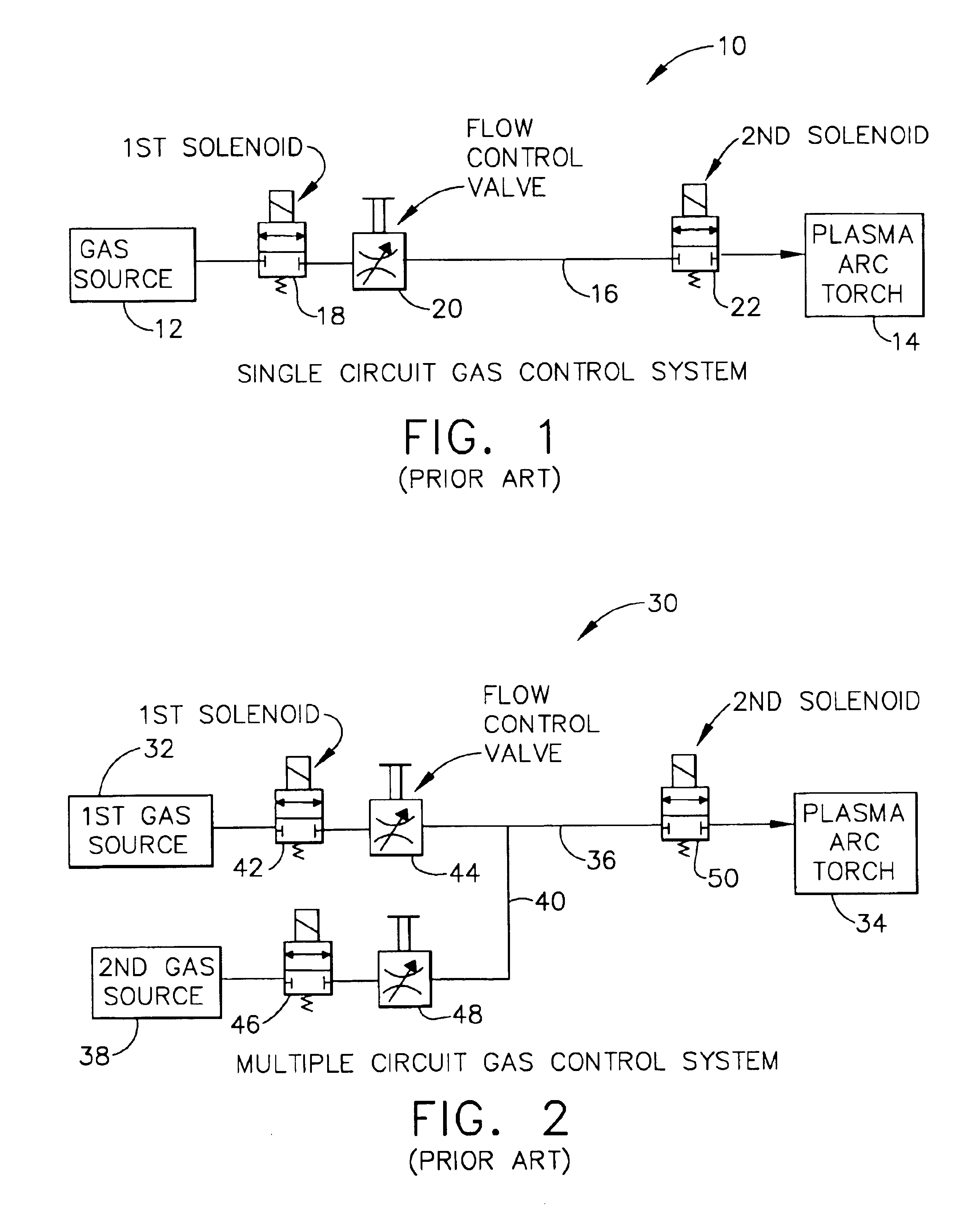
[0030]Referring to FIG. 1, a prior art single circuit gas control system 10 is shown that comprises a gas source 12, a plasma arc torch 14, and a length of gas conduit 16 that connects the gas source 12 to the plasma arc torch 14. The single circuit gas control system 10 also includes a first solenoid 18, a flow control valve 20, and a second solenoid 22 as shown. The flow control valve 20 and the first solenoid 18 are generally some distance from the plasma arc torch 14, (accessible to an operator), and are connected by the gas conduit 16 to the second solenoid 22, which is disposed proximate the plasma arc torch 14. The second solenoid 22 allows the gas conduit 16, except for the short length between the second solenoid 22 and the plasma arc torch 14, to be filled with gas before starting. Without the second solenoid ...


PUM

PropertyMeasurementUnit
gas pressureaaaaaaaaaa
pressureaaaaaaaaaa
energyaaaaaaaaaa

Abstract

A system for controlling gas flow from a gas source, through a gas conduit, and to a plasma arc torch during a transition from a cold flow when no arc is present to a hot flow when an arc is provided by the present invention. The system comprises a first solenoid in communication with the gas source, a second solenoid disposed proximate the plasma arc torch, and a bypass circuit in communication with the gas source and the second solenoid. The bypass circuit comprises a bypass solenoid that controls the gas pressure within the gas conduit to reduce gas flow fluctuations when transitioning from cold flow to hot flow. Additional gas control systems and methods are also provided that cause the gas pressure to be higher during cold flow, prior to arc ignition, which overcomes the rapid drop in flow that typically occurs during the transition to hot flow.

Description

FIELD OF THE INVENTION[0001]The present invention relates generally to gas control systems for plasma arc torches and more particularly to devices and methods for regulating gas pressure prior to arc ignition to reduce gas flow fluctuations when transitioning from cold flow (no arc) to hot flow (arc present).BACKGROUND OF THE INVENTION[0002]Plasma arc torches, also known as electric arc torches, are commonly used for cutting, marking, gouging, and welding metal workpieces by directing a high energy plasma stream consisting of ionized gas particles toward the workpiece. In a typical plasma arc torch, the gas to be ionized is supplied to a distal end of the torch and flows past an electrode before exiting through an orifice in the tip, or nozzle, of the plasma arc torch. The electrode has a relatively negative potential and operates as a cathode. Conversely, the torch tip constitutes a relatively positive potential and operates as an anode. Further, the electrode is in a spaced relati...

Claims


Application Information

Patent Timeline
Patent Type & Authority Patents(United States)
IPC IPC(8): B23K10/00H05H1/26H05H1/34
CPCB23K10/006H05H1/34
Inventor TATHAM, DAVID A.
Owner VICTOR EQUIP
Why Eureka
Try Eureka