Optical measurement apparatus and method for optical measurement

Inactive Publication Date: 2005-11-01
HAMAMATSU PHOTONICS KK
View PDF32 Cites 11 Cited by
  • Summary
  • Abstract
  • Description
  • Claims
  • Application Information

AI Technical Summary

Benefits of technology

[0036]The particle counting method of the present invention not only can effectively eliminate dark current pulses, but also can effectively output a comparison result signa

Problems solved by technology

However, when this optical measurement apparatus is used to perform high-precision measurements, dark current pulses emitted due to thermal fluctuations and the like, act as noise.
However, the following problems have been associated with optical measurement apparatuses that eliminate dark current pulses using the method of simultaneous measurement.
First, the apparatus is complex to manufacture and large in size, since it requires two photomultiplier tubes, two high-speed processing circuits, and simultaneous counting circuits.
However, the following problems are associated with optical measurement apparatuses that eliminate dark current pulses by providing such

Method used


Image

  • Optical measurement apparatus and method for optical measurement
  • Optical measurement apparatus and method for optical measurement
  • Optical measurement apparatus and method for optical measurement

Examples


first embodiment

[0048]First, an optical measurement apparatus according to the present invention will be described with reference to FIGS. 1-5. The optical measurement apparatus according to the present embodiment is a liquid scintillation counter.

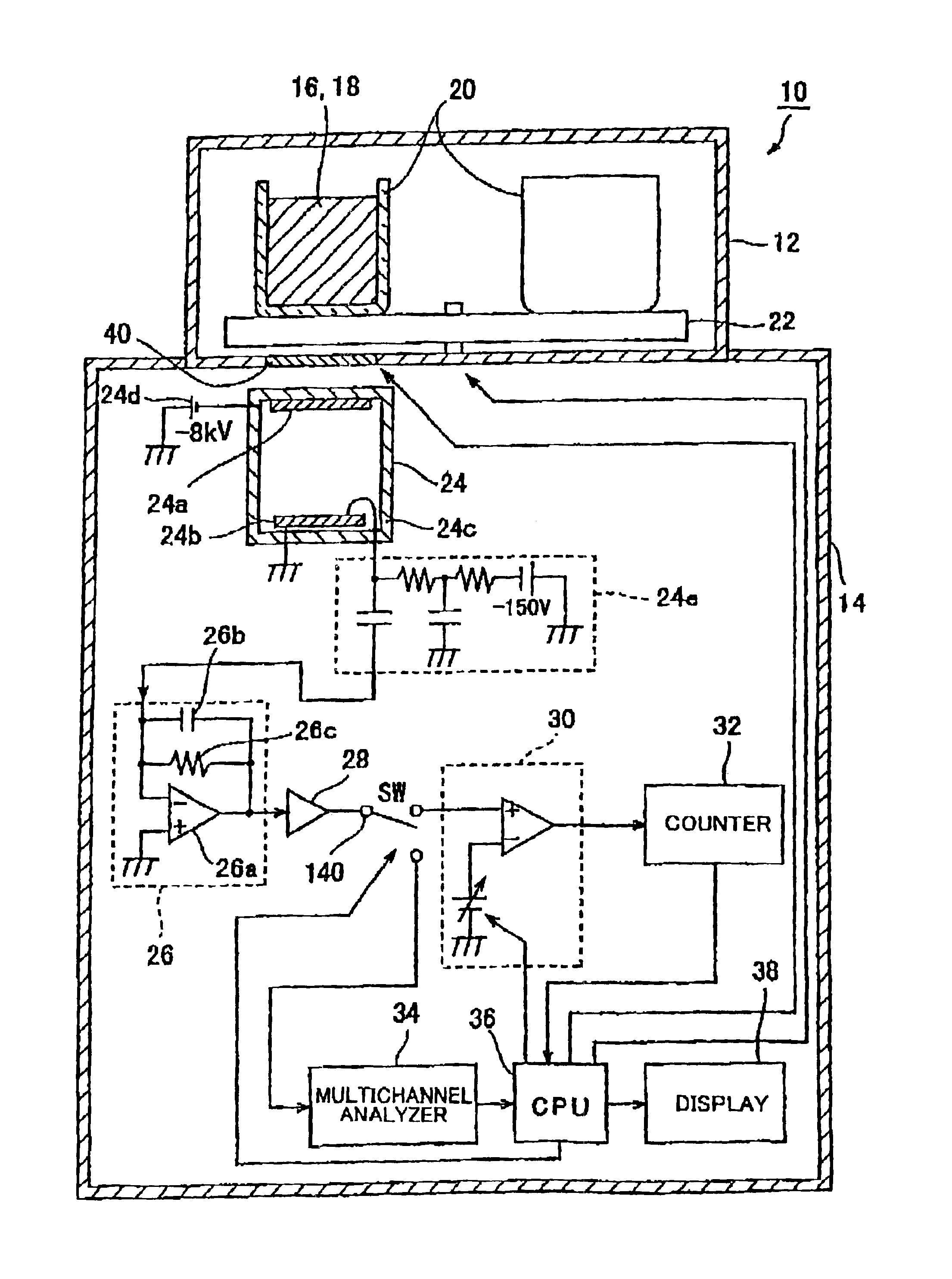
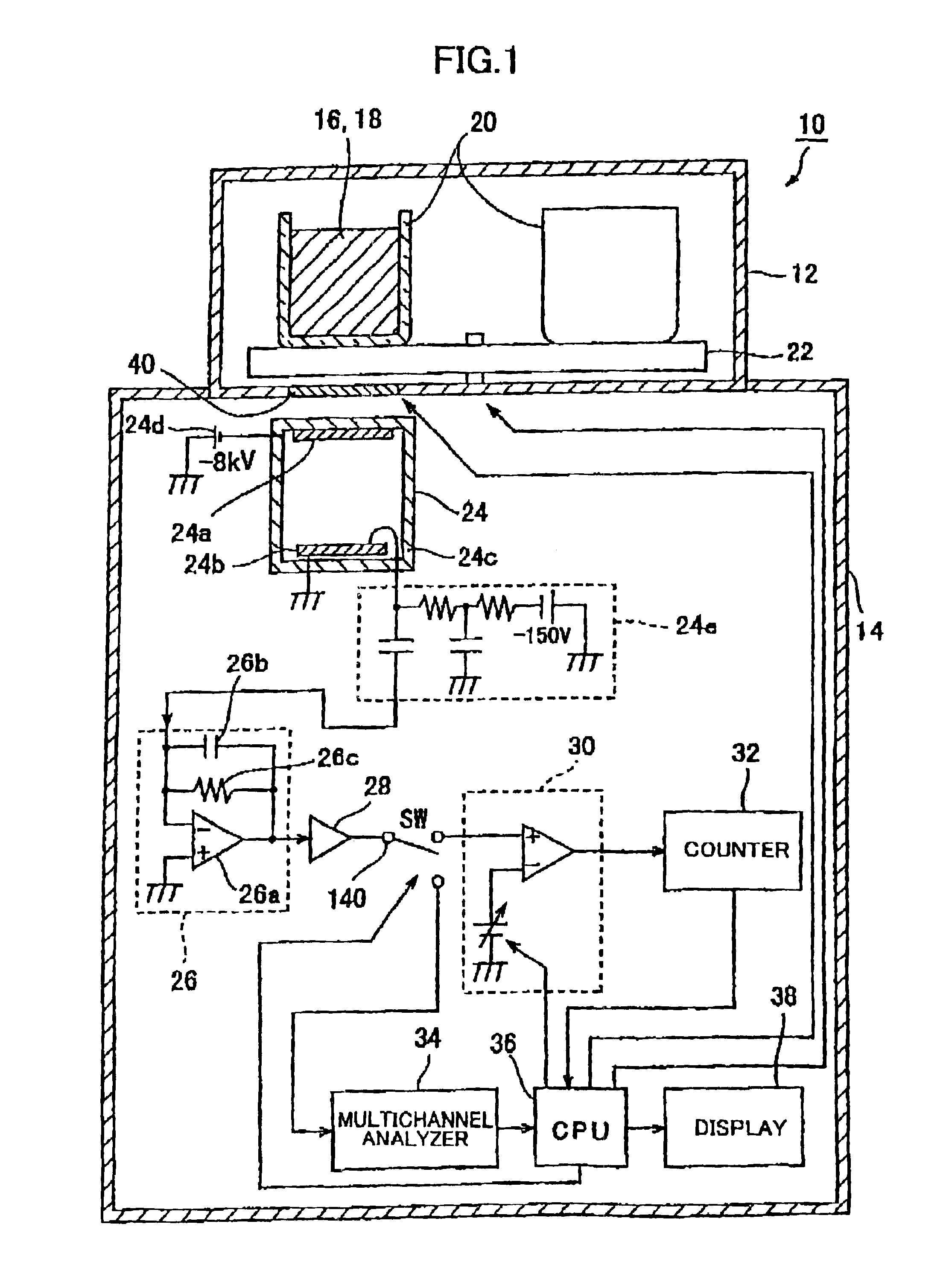
[0049]The liquid scintillation counter according to the present embodiment is for detecting the composition and the like of an object to be measured (hereinafter referred to as “sample”) by converting β rays emitted from the sample into light by a liquid scintillation and counting the scintillation light (fluorescent light). The optical measurement apparatus of the present embodiment is included in the scintillation counter according to the present embodiment. First, the construction of the liquid scintillation counter according to the present embodiment will be described. FIG. 1 shows the construction of the liquid scintillation counter according to the present embodiment.

[0050]The liquid scintillation counter 10 according to the present embodiment inclu...

second embodiment

[0095]Next, an optical measurement apparatus according to the present invention will be described with reference to FIGS. 6 and 7. The optical measurement apparatus according to the present embodiment is a particle counter.

[0096]The particle counter according to the present embodiment irradiates light on a sample such as water or air and detects scattered light that has been scattered due to foreign matter mixed in the sample, to thereby measure the particle size, and number of the foreign matter. Parts and components in the particle counter according to the present embodiment that art identical to those of the liquid scintillation counter of the first embodiment are designated by the same reference numerals to avoid duplicating description. First, the construction of the particle counter according to the present embodiment will be described. FIG. 6 shows the construction of the particle counter according to the prevent embodiment.

[0097]A particle counter 50 according to the present...


PUM


Abstract

A liquid scintillation counter 10 serving as an optical measurement apparatus includes: an HPD 24, a charge amplifier 26, a voltage amplifier 28, a comparator 30, a counter 32, a multi-channel analyzer 34, a display 38, and the like. The HPD 24 has a photocathode 24a and an APD 24b for outputting a signal that corresponds to the number of incident photons. The comparator 30 outputs a logic pulse signal, serving as a comparison result signal, only when the signal outputted from the HPD 24 and amplified by the charge amplifier 26 and voltage amplifier 28 is larger than a prescribed threshold value. This threshold value is set larger than an output signal that is outputted when a single photoelectron is emitted from the photocathode 24a and smaller than another output signal that is outputted when two or more photoelectrons are emitted.

Description

TECHNICAL FIELD[0001]The present invention relates to an optical measurement apparatus such as a scintillation counter, particle counter, and the like, and a method for optical measurement such as a method of scintillation counting, a method of particle counting, and the like.BACKGROUND ART[0002]For example, an optical measurement apparatus employing a photomultiplier tube is well known in the art for measuring weak light, such as fluorescent light emitted from a scintillator. The photomultiplier tube includes a photocathode that emits photoelectrons that correspond to the amount of light of an incident beam, and a multiplying unit for amplifying and outputting the photoelectrons emitted from the photocathode. Accordingly, the amount of light of the incident beam can be measured by counting the number of pulse currents outputted from the photomultiplier tube.[0003]However, when this optical measurement apparatus is used to perform high-precision measurements, dark current pulses emi...

Claims


Application Information

Patent Timeline
IPC IPC(8): G01J1/18G01N21/64G01J1/42G01J11/00G01N1/02G01N15/06G01N15/14G01T1/17G01T1/204G01T1/208H01J40/02H01J43/12H01J43/30H01L27/144H01L31/10H01L31/101H01L31/107
CPCG01J1/18G01J1/42G01T1/17H01L27/144H01L31/101H01L31/107
Inventor SUYAMA, MOTOHIROKAWAI, YOSHIHIKOMORITA, TETSUYAOBA, KOICHIRO
Owner HAMAMATSU PHOTONICS KK
Why Eureka
Try Eureka