IR diode based high intensity light

a diode and high intensity technology, applied in the field of infrared light assembly, can solve the problems of high temperature generated by known infrared light sources, material problems, and inability to meet the needs of light, and achieve the effects of increasing the complexity and and reducing the cost of infrared light sources

Inactive Publication Date: 2005-11-01
HONEYWELL INT INC
View PDF31 Cites 29 Cited by
  • Summary
  • Abstract
  • Description
  • Claims
  • Application Information

AI Technical Summary

Benefits of technology

[0007]Emitted infrared light may tend to diverge greatly and lose its intensity as it radiates from its source. As a result, known infrared light sources may require reflectors in order to produce a desired beam of infrared light. However, reflectors may increase the complexity and cost of the infrared light source.
[0008]In light of the shortcomings of known infrared light sources, a need exists for an improved infrared light assembly that is adapted to produce a high intensity, concentrated beam of infrared light. Another need exists for an improved method of dissipating the heat generated by an infrared light source so that it maintains peak emission. A need also exists for an infrared light assembly that requires less power to operate in order to minimize the thermal signature of the infrared light. Still another need exists for an infrared light assembly that has a longer product life.

Problems solved by technology

Known infrared light sources may generate a substantial amount of heat.
Thus, the wavelengths past 930 nm may not only be unnecessary, but also detrimental due to the high temperatures.
The high temperatures generated by known infrared light sources may have many detrimental effects.
The high temperatures may lead to material problems.
The high temperatures may also lead to failure of the infrared light source (a searchlight, for example) and the surrounding components as well as the halogen bulb itself.
In addition, the high temperatures may cause lack of covertness.
Emitted infrared light may tend to diverge greatly and lose its intensity as it radiates from its source.
However, reflectors may increase the complexity and cost of the infrared light source.

Method used


Image

  • IR diode based high intensity light
  • IR diode based high intensity light
  • IR diode based high intensity light

Examples


Embodiment Construction

)

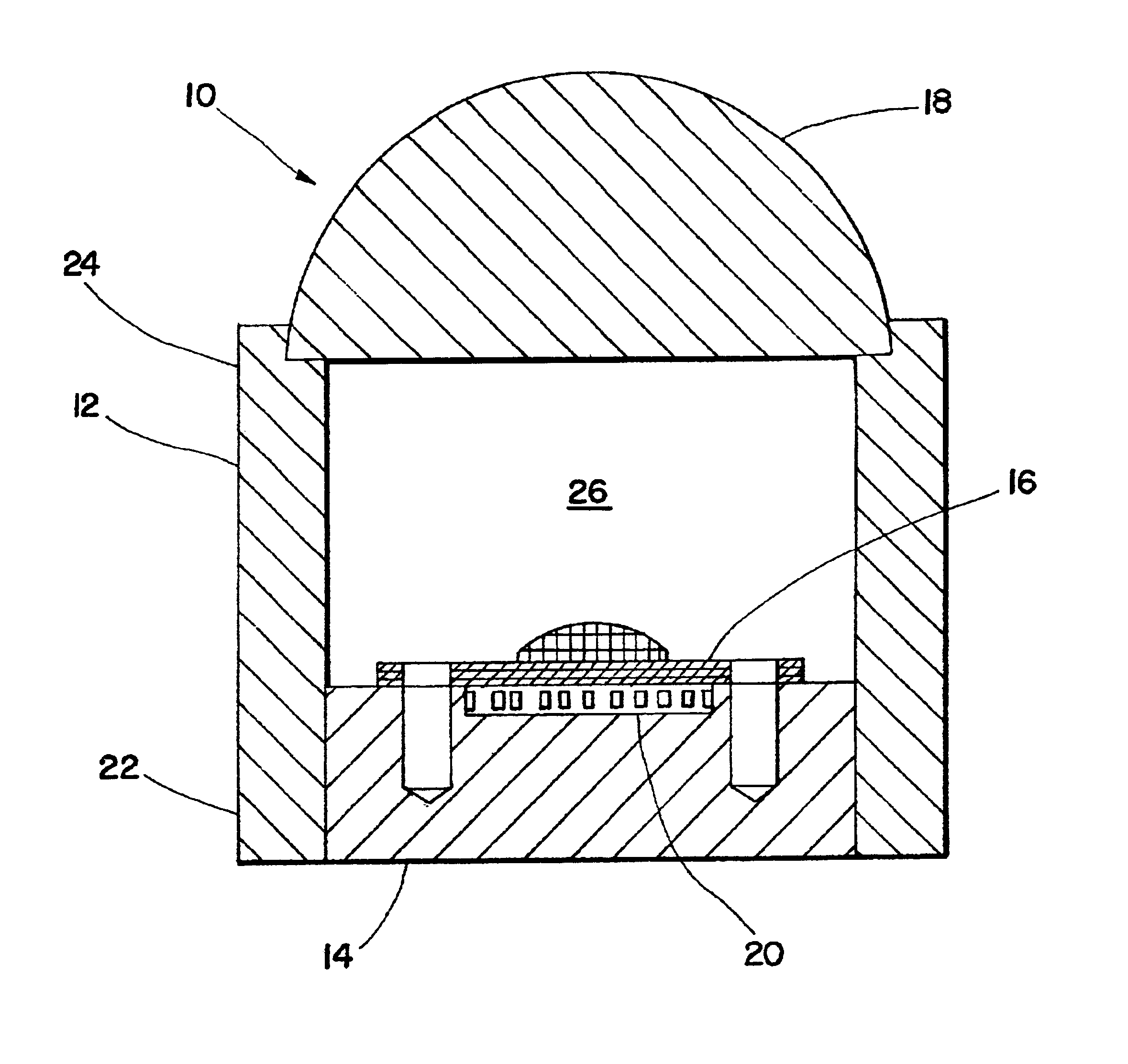
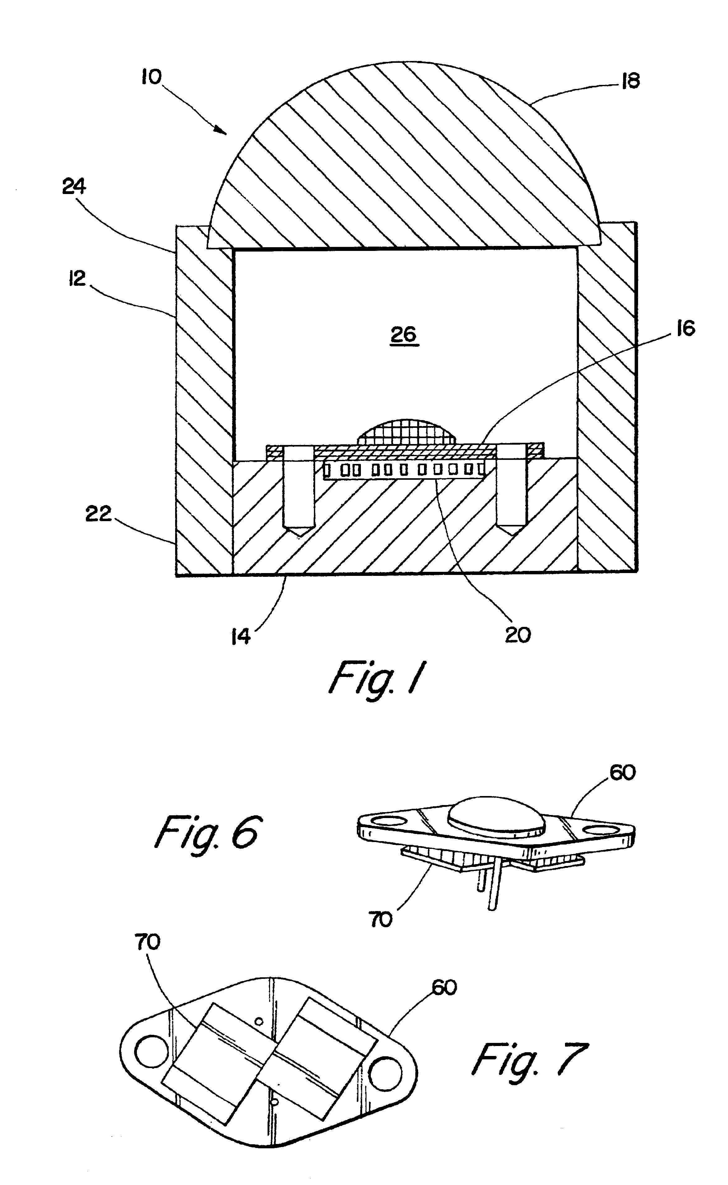
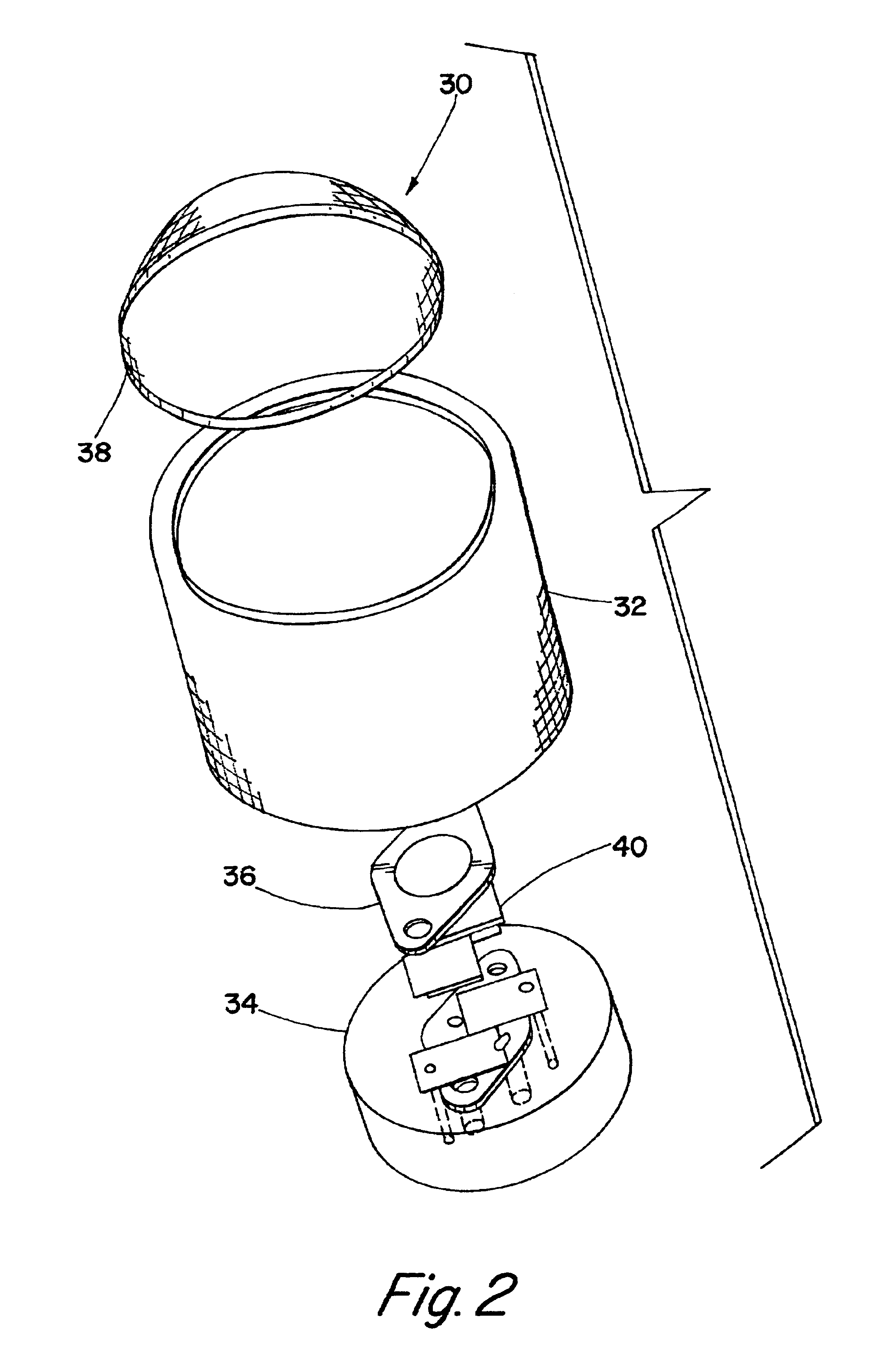
[0025]The present invention is directed to an infrared light assembly. Preferred embodiments of the infrared light assembly of the present invention may be used on aircraft or other vehicles for landing, taxi mode, or search operations. Preferred embodiments of the infrared light assembly of the present invention may also be used in many other applications which utilize infrared light.

[0026]FIG. 1 shows one embodiment of a light assembly of the present invention. The light assembly 10 is comprised of a housing 12, a base 14, an IR light emitting diode 16, an aspheric lens 18, and optional thermal electric coolers 20. The light assembly 10 preferably only requires about 10 to about 20 watts to operate, and it preferably provides a collimated beam of infrared light having a NVIS radiant intensity greater than about 2. However, those skilled in the art should recognize that the power requirement and the radiant intensity of the emitted infrared light may vary based on the components, ...


PUM


Abstract

The present invention is directed to an infrared light assembly (10, 30, 80, 90). A preferred embodiment of the light assembly (10, 30, 80, 90) may be used on aircraft or other vehicles for landing, taxi mode, or search operations. The light assembly (10, 30, 80, 90) preferably only requires about 10 to 20 watts of power. The light assembly (10, 30, 80, 90) may include a housing (12, 32, 82), a base (14, 34, 50), an IR diode (16, 36, 60), and an aspheric lens (18, 38). The base (14, 34, 50) is preferably connected to the bottom portion (22) of the housing(12, 32, 82), and the aspheric lens (18, 38) is preferably connected to the top portion (24) of the housing (12, 32, 82). The IR diode (16, 36, 60) may be mounted on the base (14, 34, 50). The housing (12, 32, 82) and the base (14, 34, 50) preferably have high thermal conductivity, and they preferably act as heat sinks. In addition, a plurality of thermal electric coolers (20, 40, 70) may be positioned between the base (14, 34, 50) and the IR diode (16, 36, 60) for additional dissipation of the heat generated by the light assembly. The IR diode (16, 36, 60) is adapted to emit infrared light. The light assembly (10, 30, 80, 90) preferably maintains a substantially constant operating temperature so that the peak emission of the IR diode (16, 36, 60) is substantially maintained. The infrared light may radiate through the hollow of the housing(12, 32, 82) to the aspheric lens (18, 38). The aspheric lens (18, 38) is preferably adapted to collimate infrared light. As a result, the light assembly (10, 30, 80, 90) may provide a collimated beam of infrared light having a NVIS radiant intensity greater than about 2.

Description

BACKGROUND AND SUMMARY OF THE INVENTION[0001]This is a continuation-in-part of U.S. patent application Ser. No. 09 / 217,221, filed Dec. 21, 1998 now abandoned.[0002]The present invention relates generally to a light assembly, and more particularly, to an infrared light assembly that may be used on aircraft or other vehicles for landing, taxi mode, or search operations.[0003]Infrared light sources may be useful in many different applications. For example, the military has extensively used infrared light sources for strategic military operations to provide night vision of terrain, people, objects, and targets. An infrared light source may be secured to an airplane, helicopter, or practically any other vehicle for use as a head light or a search light. In addition, an infrared light source may be used in a hand-held searchlight, or it may be mounted on a weapon such as a gun to provide an aiming light. In addition, infrared light sources may be used in many other military and non-milita...

Claims


Application Information

Patent Timeline
Patent Type & Authority Patents(United States)
IPC IPC(8): B64D47/02B64D47/00F21V5/04F21V5/00F21V29/00H01L33/00H01L33/48H01L33/58H01L33/64
CPCB64D47/02F21V5/048F21V29/00H01L33/483H01L33/645B64C2027/8236F21Y2101/02H01L33/58F21Y2115/10
Inventor MACHI, NICOLO F.
Owner HONEYWELL INT INC
Why Eureka
Try Eureka