Method and apparatus of asymmetric injection into subsonic flow of a high aspect ratio/complex geometry nozzle

a complex geometry, asymmetric injection technology, applied in the direction of waterborne vessels, vessel parts, vessel construction, etc., can solve the problems of increasing the temperature of the exhaust flow, the thrust of the engine, and the reduction of the effective throat area of the nozzle, so as to improve the blending and integration of the aircraft, reduce complexity, and improve the effect of durability

Inactive Publication Date: 2005-11-08
LOCKHEED MARTIN CORP
View PDF25 Cites 26 Cited by
  • Summary
  • Abstract
  • Description
  • Claims
  • Application Information

AI Technical Summary

Benefits of technology

[0016]Another technical advantage of the present invention is that an aircraft equipped with an engine and fixed-geometry nozzle using pulsed injection can be implemented to non-circular exhaust aperture shapes typical of advanced fighter concepts. These aperture shapes, such as elliptical or diamond shapes, allow for better blending and integration into the aircraft aft body structure than typical iris-type nozzles.
[0017]Another technical advantage of the present invention, particularly when a fixed geometry nozzle is used, is that alternative materials can be used for the nozzle structure with an eye towards thermal rather than mechanical constraints. For instance, ceramic materials can form a fixed nozzle supported directly by the structure of the aircraft. Such ceramic materials can provide a heavy duty heat resistance nozzle structure with much improved durability compared to conventional metal and carbon materials. The reduced complexity of such a fixed nozzle system will reduce the cost of operating and maintaining the aircraft and can increase the efficiency of operating the aircraft due to the significantly reduced weight of such a system. Further, a nozzle incorporated with the aircraft's structure can be shaped to minimize drag, thus increasing the aircraft's efficiency and range.
[0018]Another technical advantage of the present invention is that an asymmetric secondary flow can provide vectoring of an engine's thrust. Thrust vectoring can allow aircraft control of pitch and yaw at all flying speeds, and can decrease the surface area of control surfaces, resulting in reduced aircraft drag and weight.
[0019]Another technical advantage of the present invention is that a fixed geometry nozzle can provide a combination of throttling and vectoring functions. Opposing injectors can provide throttling with nozzle blockage according to their combined mass flow and pulsing characteristics while also providing vectoring by varying the distribution of the total secondary flow between the injectors.
[0020]The pulsed injection system of the present invention offers additional technical advantages over previously developed injection techniques. Pulsed or unsteady injection of a fluidic secondary flow can provide improved penetration into the fluidic flow compared to the penetration provided by steady state injection. This increased penetration enhances the blockage of the nozzle opening without increasing the time averaged mass flow of the injected secondary flow. Thus, the effective cross sectional area of a nozzle and its vectoring angle can be controlled with less overall fluidic secondary flow injection. This increases the efficiency of the engine since less compressed air is needed by a pulsed secondary flow compared to a steady state secondary flow, and also decreases the size of the ducts needed to provide air to the injectors.

Problems solved by technology

Afterburners add fuel to the exhaust chamber and ignite the fuel in the exhaust chamber, which increases the temperature of the exhaust flow.
Although the energy added by afterburned fuel can greatly increase the thrust of the engine, the reduced density of the hotter air requires a larger nozzle effective throat area.
Failure to increase nozzle effective area during afterburning with a typical jet engine can cause excessive back pressure in the compressor section and turbine section, causing the engine to stall.
Although variable geometry nozzles allow the use of afterburner, they also have many inherent disadvantages which penalize aircraft performance.
Such nozzles are typically made of large, heavy metal flaps which mechanically alter nozzle geometry by diverting exhaust low with physical blockage, and thus have to endure the high temperatures and pressures associated with exhaust gases.
In the iris-type nozzles typically used on afterburner-equipped engines, the actuators used to adjust the nozzle flaps to appropriate positions in the exhaust flow tend to be heavy, expensive and complex because of the forces presented by the exhaust flow which the nozzle flaps must overcome.
These leaks cause reductions in thrust.
Variable geometry nozzles are also difficult to implement on exotic nozzle aperture shapes typical of advanced tactical fighter aircraft.
Attempts to reduce the disadvantages of variable geometry nozzles have had limited success.
Although the two-dimensional nozzle flaps of the Raptor provide better infrared and radar cross section characteristics than can be obtained from typical iris-type nozzles, even the Raptor's advanced system suffers from the above-mentioned disadvantages.
For instance, air can leak along the intersection of the two-dimensional nozzle flaps, introducing inefficiency.
Attempts to use a fixed geometry nozzle with afterburning engines have met with only limited success due to the difficulty of maintaining flow through the engine when an overpressure is created by afterburner initiation.
However, this system requires modification to the engine and other complexities such as a control program to monitor and adjust pressure produced by the compression section.
Although the injection of a secondary flow will support a fixed geometry nozzle in an afterburning jet engine, this method also introduces inefficiencies to the engine's operation.
For instance, the amount of afterburning may be limited due to the lower effectiveness of secondary injection compared to the effectiveness of variable geometry nozzles.
Also, injection of air across the flow of the exhaust tends to use a large amount of high pressure air to obtain effective nozzle blockage.
Thus, injection can introduce inefficiency because the total momentum of the exhaust flow is decreased by the decreased flow from the compressor section into the combustion section if compressed air is bled from the compressor section for injection.
This inefficiency can result in a reduced range of operations for a given fuel supply and a fuel flow.

Method used


Image

  • Method and apparatus of asymmetric injection into subsonic flow of a high aspect ratio/complex geometry nozzle
  • Method and apparatus of asymmetric injection into subsonic flow of a high aspect ratio/complex geometry nozzle
  • Method and apparatus of asymmetric injection into subsonic flow of a high aspect ratio/complex geometry nozzle

Examples


Embodiment Construction

[0034]Preferred embodiments of the present invention are illustrated in the FIGUREs, like numerals being used to refer to like and corresponding parts of the various drawings.

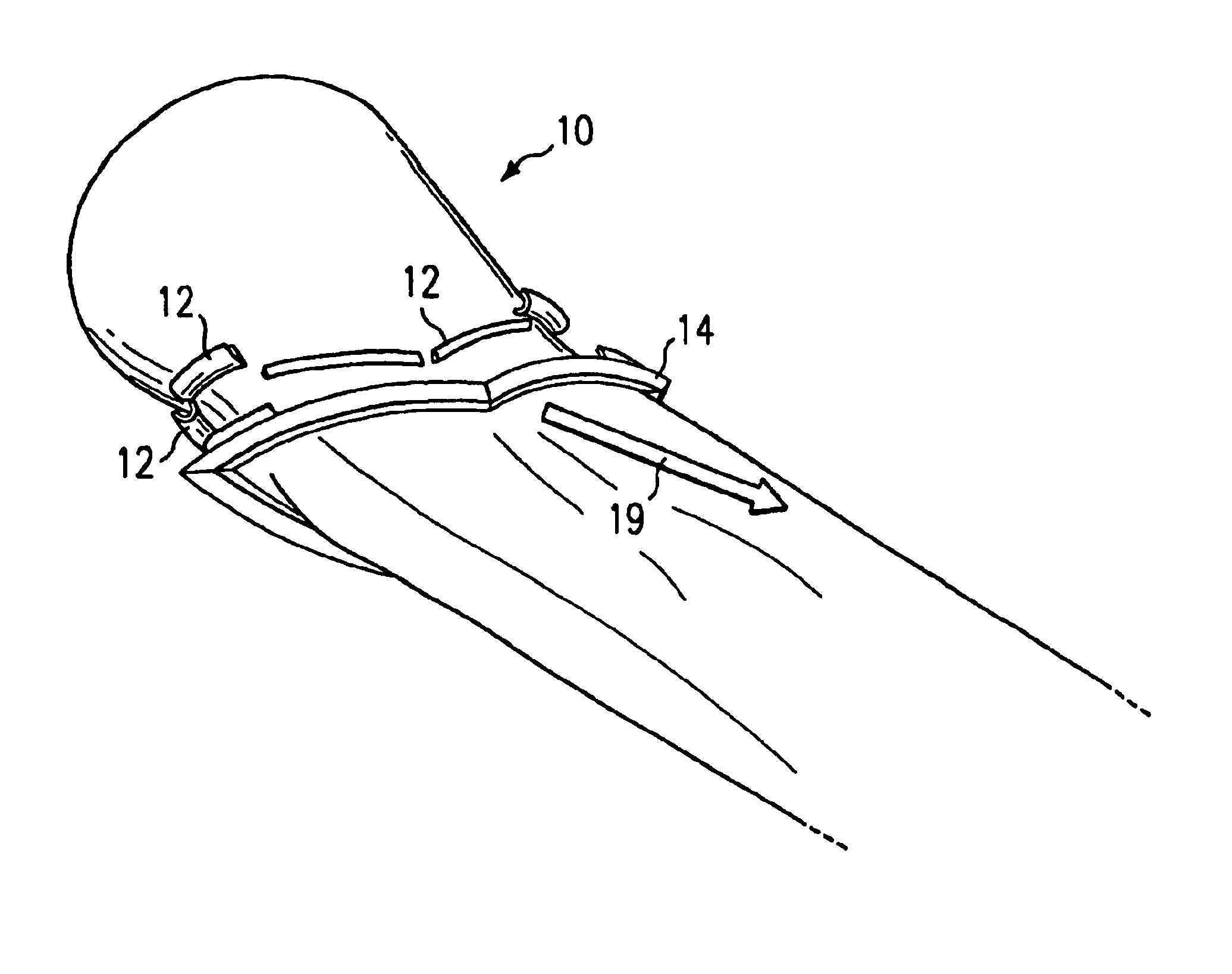
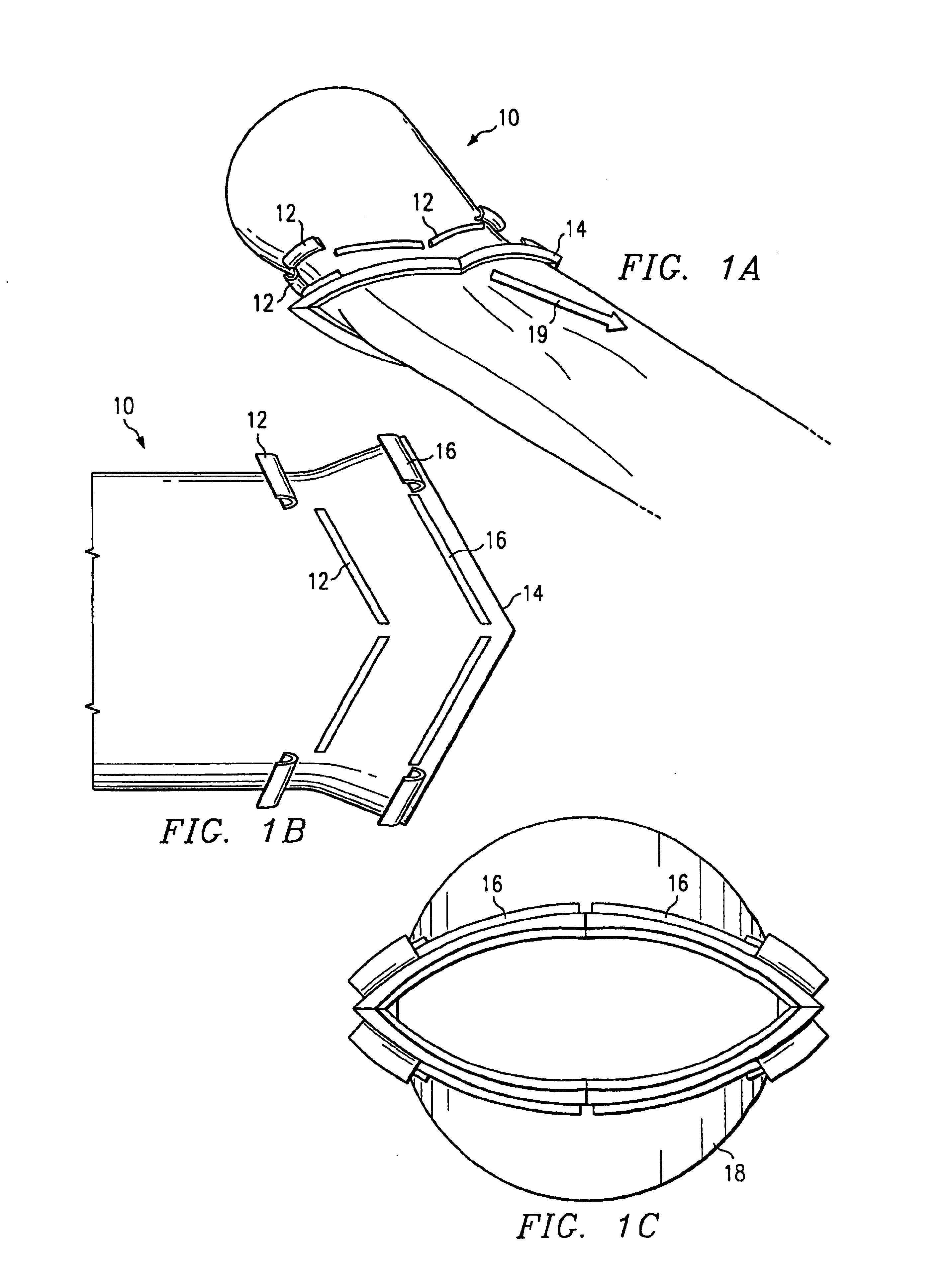
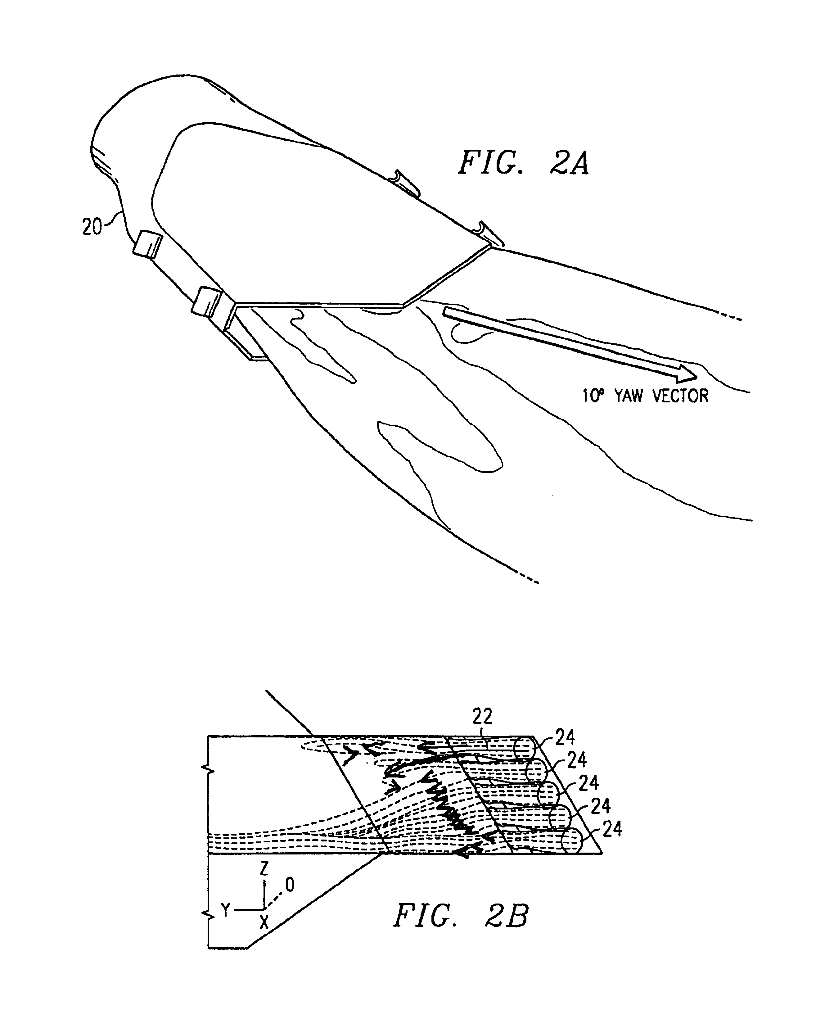
[0035]The present invention reveals a method and apparatus for controlling the effective area and thrust vector angle of a fluid flow. In one embodiment, the fluid flow is controlled in an advanced, high aspect ratio, complex aperture geometry nozzle using asymmetric injection into the subsonic portion of the fluid flow.

[0036]Fluidics alter the mass flow and direction of a main fluid stream, or primary fluid flow, by the introduction of small control jets. Small disturbances created by injectors at points along the primary fluid flow produce large responses in the main stream. Fluidic injection is used to provide internal flowpath shape variation for jet control in nozzles and holds the promise of reducing the weight and complexity of future exhaust systems by eliminating mechanical flowpath actuation. By intro...


PUM


Abstract

The present invention reveals a method and apparatus for controlling the effective area and thrust vector angle of a fluid flow. In one embodiment, the fluid flow is controlled in an advanced, high aspect ratio, complex aperture geometry nozzle using asymmetric injection into the subsonic portion of the fluid flow. The present invention vectors the primary flow by partially blocking the flow with an opposed flow across the flow field. A fluidic flow field is defined in a flow container that directs a pressurized, primary fluidic flow from the container towards an exit of the container. A nozzle may cooperate with the exit of the flow container to control the fluidic flow as it exits the flow container. One or more injectors associated with the container are proximate to the effect throat of the primary flow while other are located downstream of to introduce an opposing fluidic flow that interacts with the primary fluidic flow. A controller associated with the injectors directs the injectors to provide the opposing flow as needed to achieve a desired partial blockage of the primary flow, thereby vectoring the primary flow.

Description

RELATED APPLICATIONS[0001]This application claims the benefit of U.S. patent application Ser. No. 08 / 906,731 filed on Aug. 5, 1997, now U.S. Pat. No. 6,112,512, entitled “Method and Apparatus of Pulsed Injection for Improved Nozzle Flow Control.” Additionally, this application claims priority to and repeats a substantial portion of prior application entitled “Method and Apparatus of Pulsed Injection for Improved Nozzle Flow Control” filed on Aug. 5, 1997 which was accorded Ser. No. 08 / 906,731. Since this application names the inventor named in the prior application, the application constitutes a continuation in part of the prior application. This application incorporates by reference prior U.S. patent application Ser. No. 08 / 906,731 filed on Aug. 5, 1997, now U.S. Pat. No. 6,112,512, entitled “Method and Apparatus / of Pulsed Injection for Improved Nozzle Flow Control” and U.S. patent application Ser. No. 08 / 906,768 filed on Aug. 5, 1997, now U.S. Pat. No. 6,112,513, entitled “Method ...

Claims


Application Information

Patent Timeline
Patent Type & Authority Patents(United States)
IPC IPC(8): F02K1/28F02K1/00F02K1/30
CPCF02K1/28F02K1/30
Inventor MILLER, DANIEL N.YAGLE, PATRICK J.GINN, KERRY B.HAMSTRA, JEFFREY W.
Owner LOCKHEED MARTIN CORP
Why Eureka
Try Eureka