Eureka AIR delivers breakthrough ideas for toughest innovation challenges, trusted by R&D personnel around the world.

Drive arrangement for a weaving loom and shedding machine

Inactive Publication Date: 2005-11-08
LINDAUER DORNIER GMBH
View PDF24 Cites 11 Cited by
  • Summary
  • Abstract
  • Description
  • Claims
  • Application Information

AI Technical Summary

Benefits of technology

[0014]The reverse is true correspondingly in that, compared to the weaving machine, a slower braking action can be applied to return the shed forming machine to a stillstand. See in this connection the German Patent Application DE 100 53 079. As a result, the required acceleration and braking moments for the drive of the shed forming machine can be reduced. Therefore, and due to the above mentioned degrees of freedom in the motion during current operation it is not necessary to dynamically optimize the characteristics of the drive motor of the shed forming machine. Rather, the drive motor of the shed forming machine can now be optimized with regard to consumption. On the other hand, the drive of the main drive shaft of the weaving machine can now also be made smaller because it is relieved by the shed forming machine and because it is additionally favored by the lighter construction of respective gear stages of the weaving machine. The acceleration moment particularly required for the starting operation has become smaller.
[0027]Furthermore, the arrangements according to the invention make possible a higher insensitivity to weak or fluctuating electrical power supply networks during the starting phase and thus also during the braking phase because for the critical weaving machine start the kinetic energy of the shed forming machine is also utilized. For example, when the power supply network has a voltage lower than the rated voltage of the network, the shed forming machine is accelerated to a higher r.p.m. so that the shed forming machine with its higher kinetic energy compensates the lower energy supply from the power supply network.

Problems solved by technology

The resulting torsions cause vibrations which are transmitted onto the entire structure.
Such vibrations may lead to impairments of the weaving quality.
Such vibrations also have a high power consumption of the drive system and a high dead time frequency of the entire machine.
Further, the interlocking connection between the weaving machine and the shed forming machine is subject to wear and tear as well as failure.
The above mentioned solutions are also disadvantageous with regard to the layout of the drive because the interlocking connection between the weaving machine and the shed forming machine require that both start simultaneously.
Such drives then have in most instances a thermal moment (rated moment) which is inadequate for a continuous operation so that external cooling is required, mostly with oil or water.
A further disadvantage is, that the adjustment mechanisms provided in the known solutions for the switching gear wheel or respectively for the main drive shaft are additional components subject to wear and tear which additionally entail an extra maintenance effort and expense.

Method used


Image

  • Drive arrangement for a weaving loom and shedding machine
  • Drive arrangement for a weaving loom and shedding machine
  • Drive arrangement for a weaving loom and shedding machine

Examples


Embodiment Construction

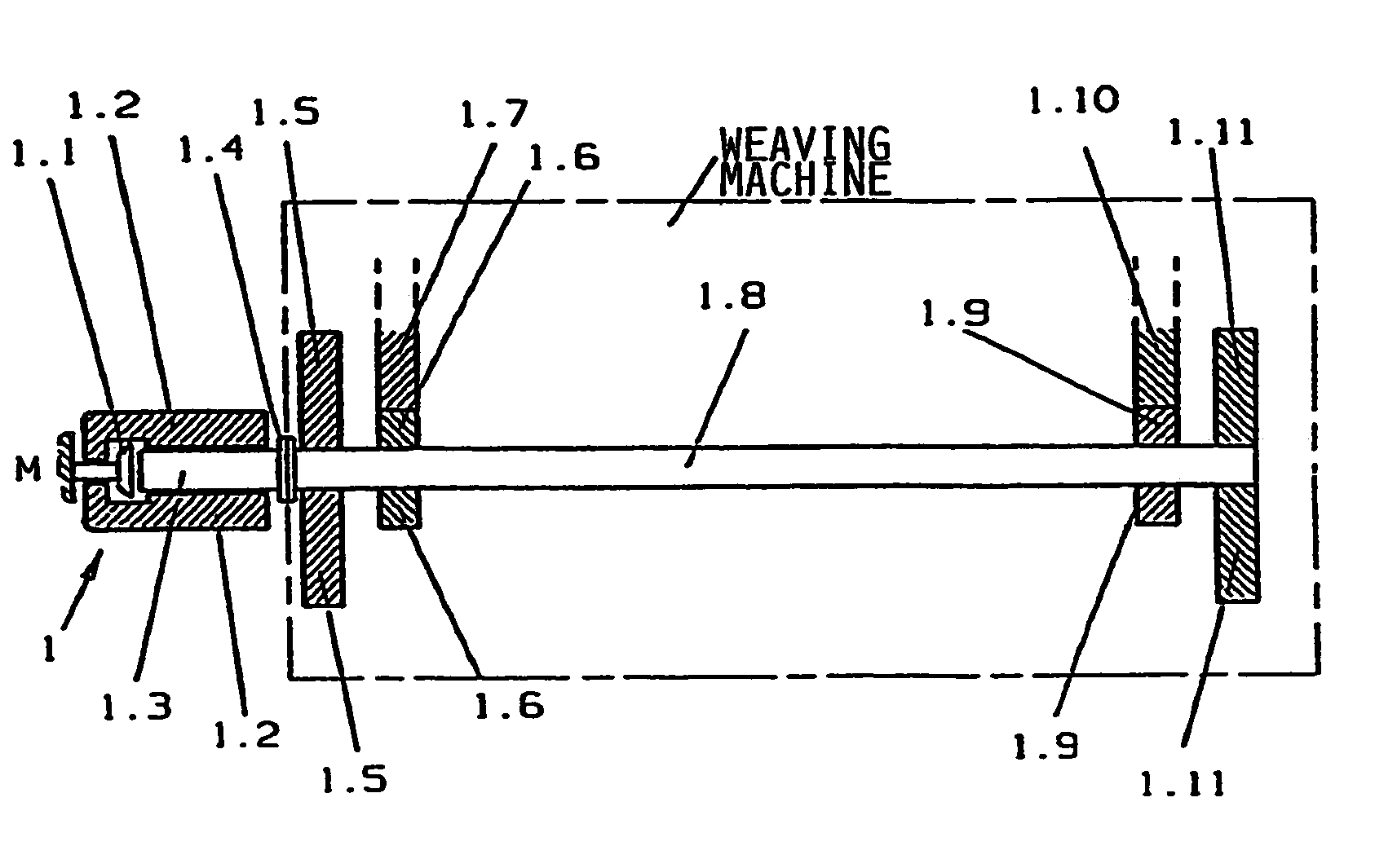
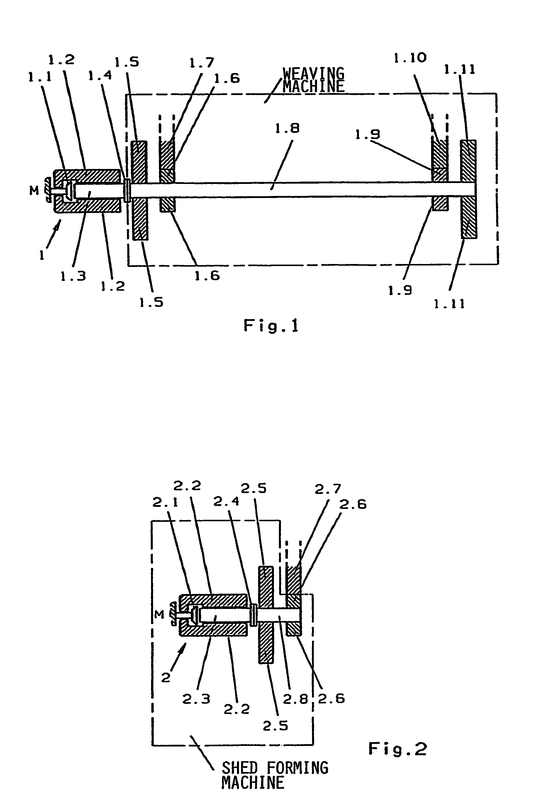
[0036]In FIG. 1 the main drive shaft 1.8 of a weaving machine is moved by a drive motor 1 comprising a stator 1.2, a rotor 1.3, and the integrated brake 1.1, whereby the latter normally performs merely the function of a holding brake for the machine stillstand. The rotor and the main drive shaft are rigidly coupled to each other through the coupling 1.4. Further, gear wheels 1.6 and 1.9 are rigidly mounted on the main drive shaft and mesh with the gear wheels 1.7 or 1.10 respectively. 1.6 and 1.7, as well as 1.9 and 1.10 thus represent the left or the right gear side of a weaving machine. The additional flywheel masses 1.5 and 1.11 are also rigidly mounted on the main drive shaft 1.8. The flywheel masses serve primarily for compensating the r.p.m. fluctuations of the drive of the weaving machine.

[0037]According to FIG. 2 the drive shaft 2.8 of a symbolically illustrated shed forming machine is driven by a separate drive motor 2. This drive motor comprises a stator 2.2 and a rotor 2....


PUM


Abstract

A drive arrangement is constructed for permitting the separate operation of a weaving machine and a shed forming machine. The drive arrangement compensates any r.p.m. variations of the weaving machine drive and of the shed forming machine relative to the drive shaft of the respective machine. This drive arrangement permits keeping the energy drawn from the electrical supply network during the start phase and the drive power to be provided for a normal operation of the weaving machine and of the shed forming machine optimally low.

Description

FIELD OF THE INVENTION[0001]The invention relates to a driving arrangement for a weaving machine and a shed forming machine with means for compensating fluctuations of the r.p.m. of the drive of the weaving and shed forming machine.BACKGROUND INFORMATION[0002]A drive is known from European EP-A 0,726,345 which is effective through transmission elements on a main drive shaft provided with a switching gear wheel. The switching gear wheel meshes in a first position with a gear wheel of at least one drive of the sley of the weaving machine and with a gear wheel at least for the drive of the shed forming means. In a second position the switching gear wheel meshes only with one of the two gear wheels.[0003]A drive for a weaving machine is known from WO 98 / 31856. The drive of which is arranged coaxially to and directly coupled to the main drive shaft. The main drive shaft of the weaving machine is shiftable by a hydraulic or pneumatic adjustment system in one direction so that the drive po...

Claims


Application Information

Patent Timeline
IPC IPC(8): D03C1/14D03D51/00D03D51/02D03C3/00D03C1/00D03C3/32D03C5/00D03C13/00
CPCD03C1/14D03C3/32D03D51/02D03C13/02D03C1/146
Inventor KRUMM, VALENTINVON ZWEHL, DIETMARLEHMANN, MICHAELMAYER, DIETER
Owner LINDAUER DORNIER GMBH
Why Eureka
Eureka Blog
Learn More