
Control for vehicle including electric motor powered by engine driven generator

Inactive Publication Date: 2005-11-08
NISSAN MOTOR CO LTD
View PDF26 Cites 38 Cited by
  • Summary
  • Abstract
  • Description
  • Claims
  • Application Information

AI Technical Summary

Benefits of technology

[0015]In one exemplary implementation of the present invention, a control system for a vehicle is provided. The vehicle has a first powertrain and a second powertrain. The first powertrain includes an engine and it is coupled with a first set of road wheels. The second powertrain includes an electric motor and it is coupled with a second set of road wheels. A generator is coupled with the engine. The generator is provided as a source of electric power for the electric motor. The control system comprises control logic for determining whether or not there is a need for a predetermined scheme, which is planned to prevent the motor from applying running resistance to the second set of road wheels. The control system also comprises control logic for executing the predetermined scheme in respo

Problems solved by technology

If torque output of the motor fails to achieve a satisfactory level, the motor may apply running resistance to the second set of road wheels.
Sufficiently high efficiency and excellent fuel economy cannot be achieved if occurrence of such running resistance is allowed.
Apparently, the inventors of the prior art proposed systems fail to address themselves to a task of solving the above-mentioned problem.

Method used


Image

  • Control for vehicle including electric motor powered by engine driven generator
  • Control for vehicle including electric motor powered by engine driven generator
  • Control for vehicle including electric motor powered by engine driven generator

Examples


Embodiment Construction

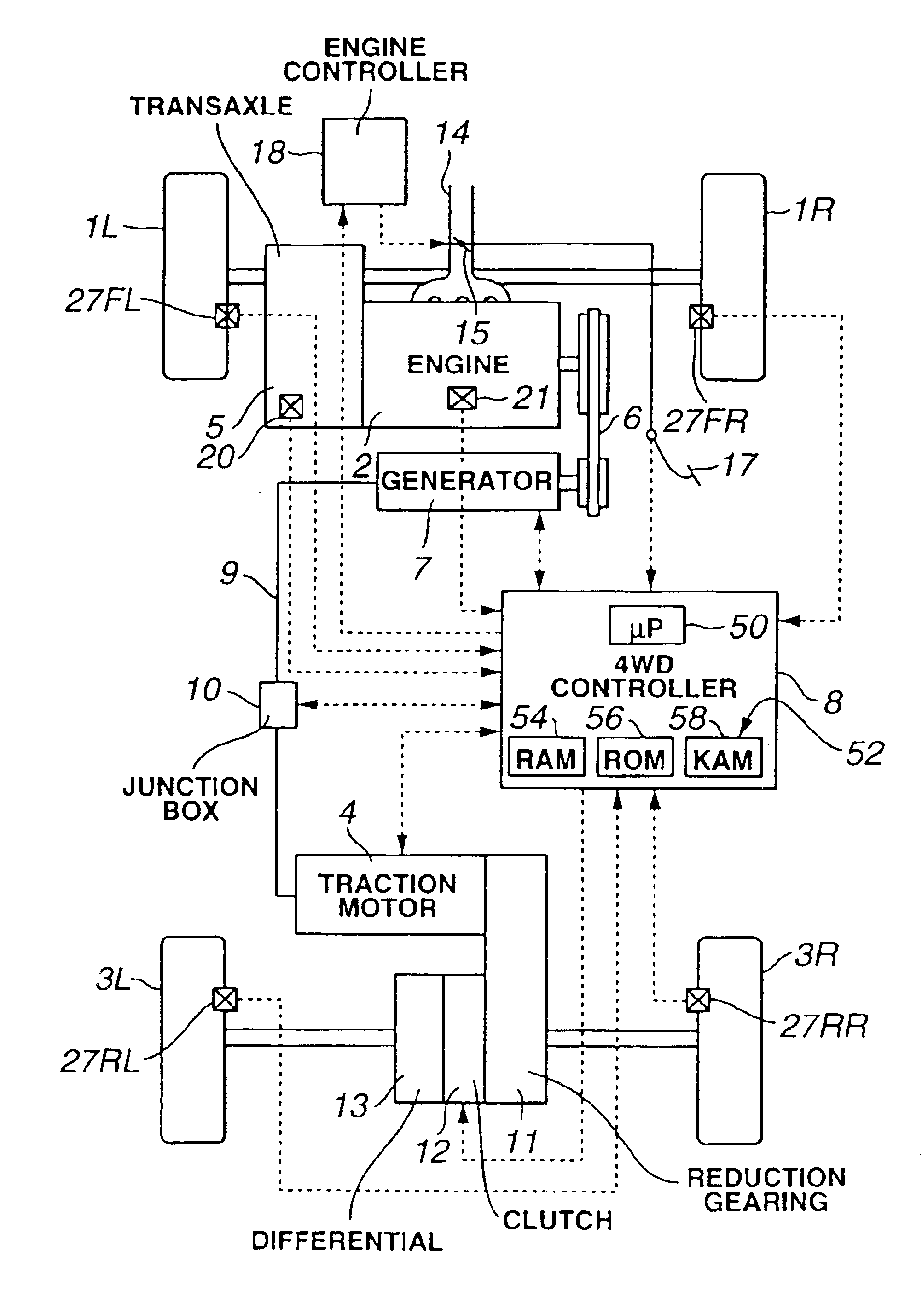
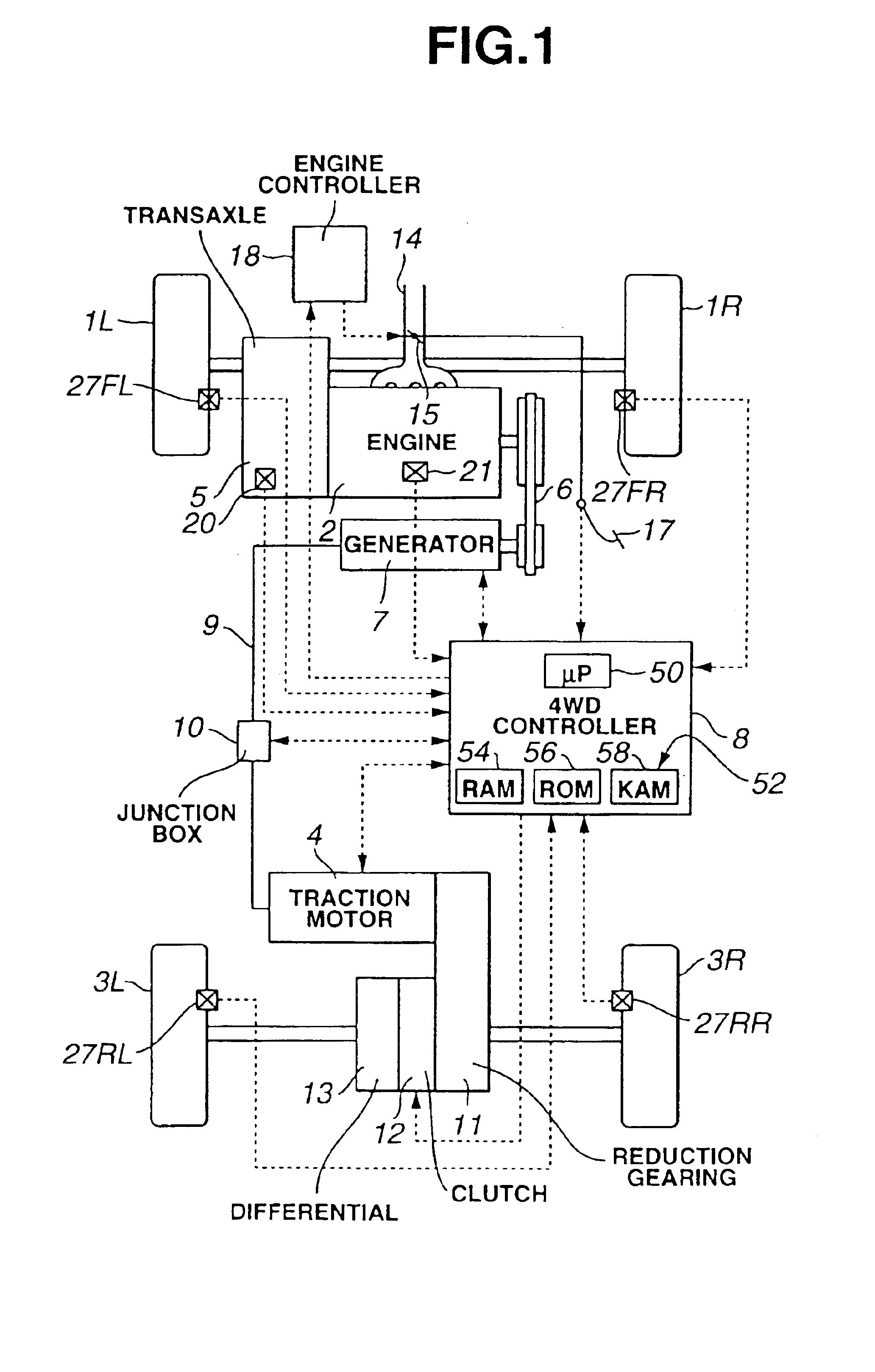
[0043]Referring now to the accompanying drawings, FIG. 1 shows a vehicle incorporating the present invention. The vehicle has a first powertrain and a second powertrain. The first powertrain includes a prime mover in the form of an internal combustion engine 2. The first powertrain is drivingly coupled with a first set of road wheels 1L and 1R. The second powertrain includes an electric motor 4 and it is drivingly coupled with a second set of road wheels 3L and 3R.

[0044]The first powertrain includes a torque converter, an automatic transmission, and a differential. The torque converter includes a pump impeller, a stator and a turbine runner. The pump impeller is coupled with a crankshaft of the engine 2 for rotation therewith. The turbine runner is coupled with an input shaft of the automatic transmission. An output shaft of the automatic transmission is coupled with the differential. The automatic transmission has various speed ratios of the input shaft to the output shaft. The dif...


PUM


Abstract

A control system for a vehicle is disclosed. The vehicle has a first powertrain and a second powertrain. The first powertrain includes an engine and it is coupled with a first set of road wheels. The second powertrain includes an electric motor and it is coupled with a second set of road wheels. A generator is coupled with the engine. The generator is provided as a source of electric power for the electric motor. The control system comprises control logic for determining whether or not there is a need for a predetermined scheme, which is planned to prevent the motor from applying running resistance to the second set of road wheels. The control system also comprises control logic for executing the predetermined scheme in response to the need.

Description

BACKGROUND OF THE INVENTION[0001]1. Field of the Invention[0002]The present invention relates to a control system and method for a vehicle with a first powertrain including an engine and a second powertrain including an electric motor powered by an engine driven generator.[0003]2. Description of the Background Art[0004]Vehicles are proposed, which have a first powertrain including an engine and an automatic transmission, and a second powertrain including an electric motor powered by a generator driven by the engine. The first powertrain is coupled with a first set of road wheels. The second powertrain is coupled with a second set of road wheels. Several examples of such vehicles are available.[0005]One such example is disclosed in Japanese Utility Model Application Pre-Grant Publication No. S55-110328, published Aug. 2, 1980. In this example, an internal combustion engine is coupled with a set of front road wheels via a transmission and a front differential gear to define a first po...

Claims


Application Information

Patent Timeline
IPC IPC(8): B60L11/12B60L11/02B60K6/04B60K6/00B60K6/20B60K6/34B60K6/387B60K6/44B60K6/52B60K17/04B60K6/547B60K17/356B60L50/15B60L50/16B60W10/02B60W10/04B60W10/06B60W10/08B60W10/10B60W10/119B60W10/12B60W20/00F02D29/00F02D29/02F02D29/06F02D45/00F16H61/02F16H63/50
CPCB60K6/44B60K6/52B60K6/547B60L11/12B60W10/02B60W10/06B60W10/08B60W10/10B60W20/00Y10T477/27B60L2240/441B60W2510/0604B60W2510/0638B60W2520/10B60W2540/10Y02T10/623Y02T10/6265Y02T10/6286Y02T10/7077Y02T10/6226Y10T477/33Y10T477/32B60K6/485B60L50/15Y02T10/62Y02T10/7072B60W20/30
Inventor KADOTA, KEIJI
Owner NISSAN MOTOR CO LTD
Learn More