Supercharge Your Innovation With Domain-Expert AI Agents!

Low cost splitter

a splitter and low-cost technology, applied in the field of power splitters, can solve the problems of increasing the size or the footprint of the power splitter package, complicating the assembly process, and increasing the cost of the cover, so as to improve the electrical characteristics and reduce the size of the packag

Inactive Publication Date: 2005-11-08
SCI COMPONENTS MINI CIRCUITS
View PDF15 Cites 3 Cited by
  • Summary
  • Abstract
  • Description
  • Claims
  • Application Information

AI Technical Summary

Benefits of technology

"The invention provides a power splitter with improved electrical characteristics in a small package size. It also provides an electronic package for the power splitter that can be used with automated surface mount manufacturing equipment. The power splitter takes up less printed circuit board space and has improved electrical repeatability. The invention also provides a method of manufacturing a low cost power splitter. The electronic package includes a case with a cavity, a top surface, and a lead mounting surface. Leads are secured to the lead mounting surface on two of the walls and have a proxil end attached to the lead mounting surface and a distal end that extends outwardly from the case. A substrate is mounted within the cavity and is surrounded by the walls. The substrate includes a first end, a second end, a top surface, a bottom surface, and a plurality of inner layers. A film resistor is formed on the top surface and a capacitor is formed on the inner layers. Terminals are located on the top surface and vias extend through the substrate between the top surface and the bottom surface. The vias electrically connect the resistor, the capacitor, and the terminals. A first transformer is attached to the bottom surface of the substrate at the first end. The first transformer has a first winding. A second transformer is attached to the bottom surface of the substrate at the second end. The second transformer has a second winding. The first and second transformers are attached to the bottom surface of the case by an adhesive. Several connector wires are connected between the terminals and the leads."

Problems solved by technology

Unfortunately, placing the resistors and capacitors beside each transformer increases the size or footprint of the power splitter package and also complicates the assembly process.
The mounting of the cover adds additional process steps and the expense of the cover.
The use of the cover also reduces the ability to cool the power splitter.
The cover causes the power splitter package to have a large height, which is undesirable in many applications.
The cover can also trap liquids used during the manufacturing process possibly leading to increased corrosion or failure.
While power splitters have been used, they have suffered from being too large, difficult to assemble and are not easily used with automated surface mount equipment.

Method used


Image

  • Low cost splitter
  • Low cost splitter
  • Low cost splitter

Examples


Embodiment Construction

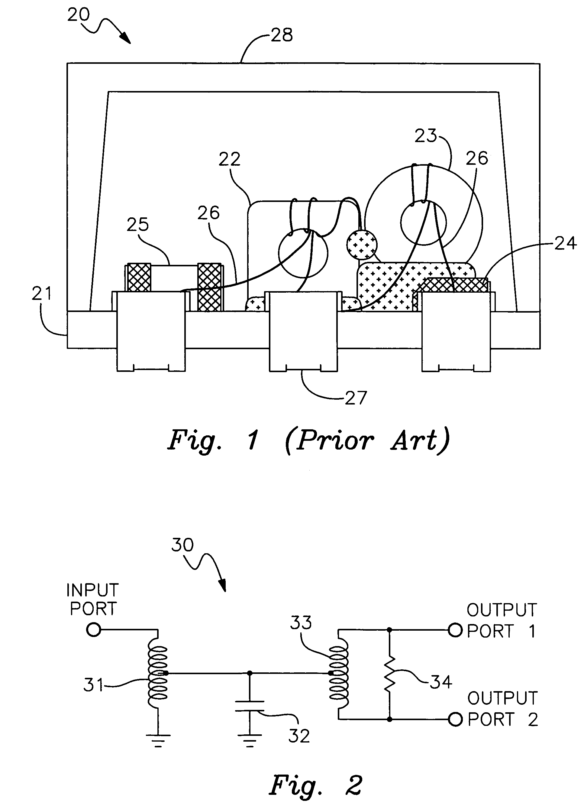
[0028]Referring to FIG. 2, a schematic diagram of a power splitter circuit 30 is shown. Power splitter 30 has an input port connected to a transformer 31. One end of the transformer 31 is connected to ground. A capacitor 32 is connected between a midpoint of transformer 31 and to ground. Another transformer 33 has a midpoint connected to capacitor 32. Transformer 33 has one end connected to output port 1 and another end connected to output port 2. A resistor 34 is connected between output ports 1 and 2. A signal applied to the input port is equally split into two signals at the output ports 1 and 2. Transformer 33 splits the input signal. Transformer 31 and capacitor 32 provide impedance matching to the input port. Capacitor 32 is required to match the reactive part of the impedance. The resistor 34 plays an important role in providing isolation between the two output ports 1 and 2. Power splitter 30 is a 2 way power splitter since the input signal is split into two output signals.

[...


PUM


Abstract

A low cost power splitter that has a small size and can be used with automated surface mount manufacturing equipment. The power splitter includes a case having a cavity and a lead mounting surface. Leads are secured to the lead mounting surface. A substrate is mounted in the cavity. The substrate has top surface, a bottom surface and inner layers. A resistor is formed on the top surface. A capacitor is formed on the inner layers. Terminals are located on the top surface and vias extend through the substrate. A pair of transformers are attached to the bottom surface and to the case by an adhesive. The transformers have windings that are connected to the terminals. Connector wires are connected between the terminals and the leads.

Description

BACKGROUND[0001]1. Field of the Invention[0002]This invention relates to power splitters used with RF and microwave frequency signals in general and more particularly to a power splitter having a small package size that can be manufactured at low cost.[0003]2. Description of the Related Art[0004]Power splitters operating at frequencies up to 3 GHz have been made with ferrite transformers along with resistors and capacitors arranged around the ferrite transformers. When the frequency range starts below 10 MHz, two ferrite cores are necessary to achieve the desired electrical performance. The power splitter components typically use chip resistors and chip capacitors packaged on a circuit board.[0005]Referring to FIG. 1, a prior art power splitter package is shown. Power splitter package 20 has a circuit board 21 upon which are mounted a pair of single core transformers 22 and 23. A chip resistor 24 and chip capacitor 25 are soldered onto circuit board 21 to one side of the transformer...

Claims


Application Information

Patent Timeline
Patent Type & Authority Patents(United States)
IPC IPC(8): H03H7/48H03H7/38H03H7/00
CPCH03H7/48
Inventor SETTY, RADHAKRISHNAIAHLU, CHEN
Owner SCI COMPONENTS MINI CIRCUITS
Features
  • R&D
  • Intellectual Property
  • Life Sciences
  • Materials
  • Tech Scout
  • Unparalleled Data Quality
  • Higher Quality Content
  • 60% Fewer Hallucinations
Learn More