Acoustic soot blower, and method for operating the same

Inactive Publication Date: 2005-11-15
MITSUBISHI HITACHIPOWER SYST LTD
View PDF8 Cites 21 Cited by
  • Summary
  • Abstract
  • Description
  • Claims
  • Application Information

AI Technical Summary

Benefits of technology

[0110]If sonic soot blowers, in which the sonic pressure becomes higher and higher in the denitration catalyst layers from the upstream stage to the downstream stage in the gas flow through a plurality of denitration layers in the denitration apparatus, are disposed in the vicinity of the respective denitration catalyst layers, the effect that prevents ash from adhering is improved.
[0111]Also, since an area where

Problems solved by technology

If the combustion ash excessively adheres to the surfaces of the above-described heat transmission tubes, heat transmission of water or steam fluid, which flows from the high temperature combustion gas to groups 3 and 4 of the heat transmission tubes, is hindered to lower the capacity of a boiler apparatus.
Therefore, the prior art soot blower 6 had a problem in that it could not be operated satisfactorily in a wide range of operating conditions of a boiler.
The reason is that a sound pressure level measurement microphone cannot be inserted into the inside of the boiler furnace because the inside of the boiler furnace is at a high temperature during the operation thereof.
Further, the temperature of the casing, in which a sonic wave oscillator of the sonic soot blower and a horn thereof are accommodated, increases due to radiant heat of a high temperature gas

Method used


Image

  • Acoustic soot blower, and method for operating the same
  • Acoustic soot blower, and method for operating the same
  • Acoustic soot blower, and method for operating the same

Examples


Embodiment Construction

[0138]A description is given of the embodiments of the invention with reference to the accompanying drawings, taking a boiler as an example.

[0139]FIG. 10 is a general sketch of the boiler, in which a burner 2 is disposed in the boiler furnace 1, a group 3 of suspension type heat transmission tubes such as a superheater, reheater, etc., are installed on the ceiling of the boiler furnace 1, and a group 4 of horizontal type heat transmission tubes such as a superheater, reheater and economizer, etc., are disposed on the rear heat transmission section of the boiler furnace 1. And, a plurality of sonic soot blowers 6 are installed on the furnace walls in the vicinity of the group 3 of suspension type heat transmission tubes and group 4 of horizontal type heat transmission tubes in the boiler furnace 1.

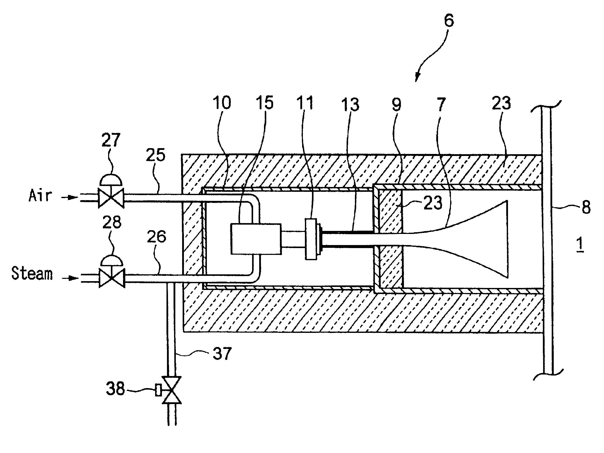
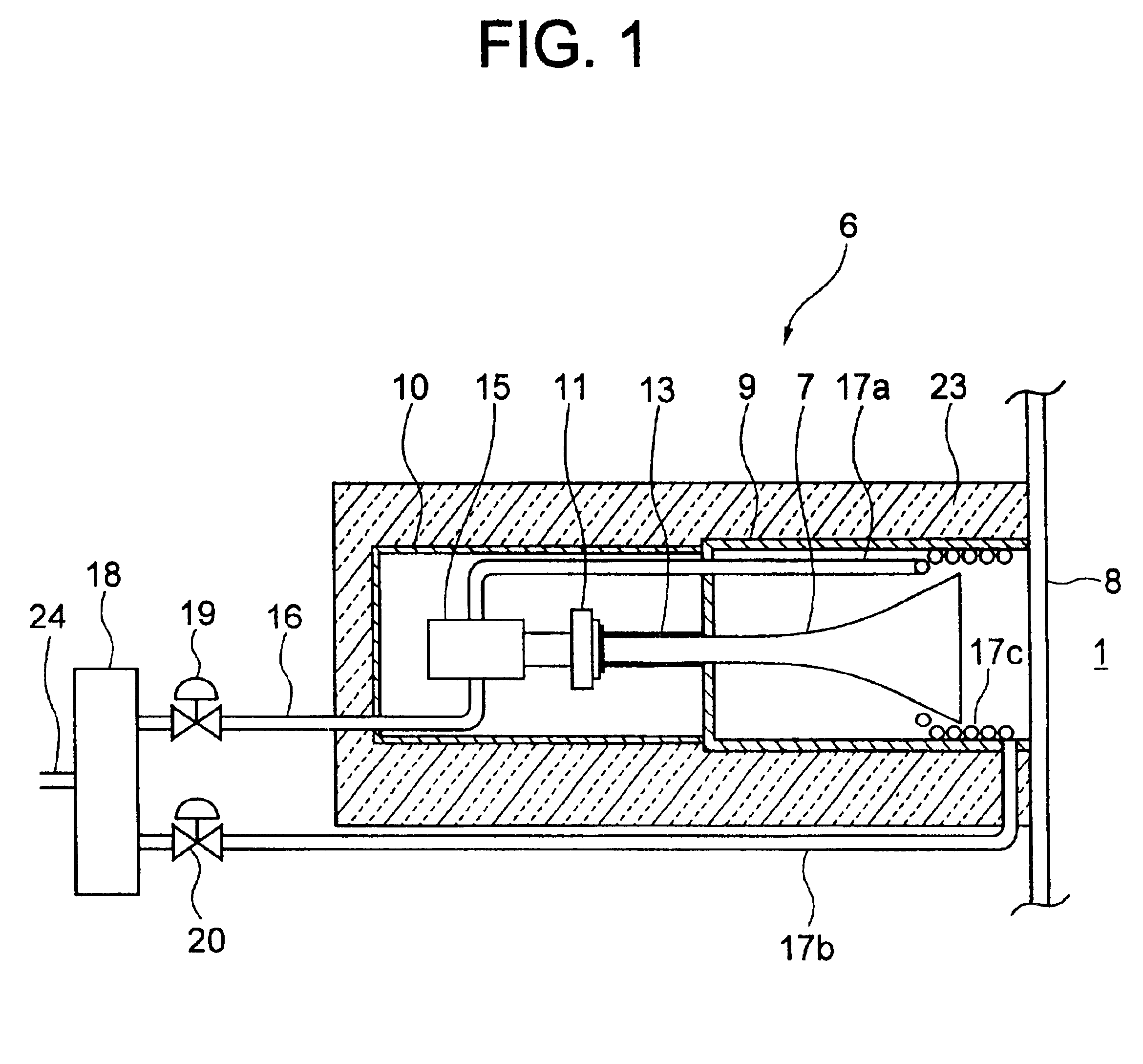
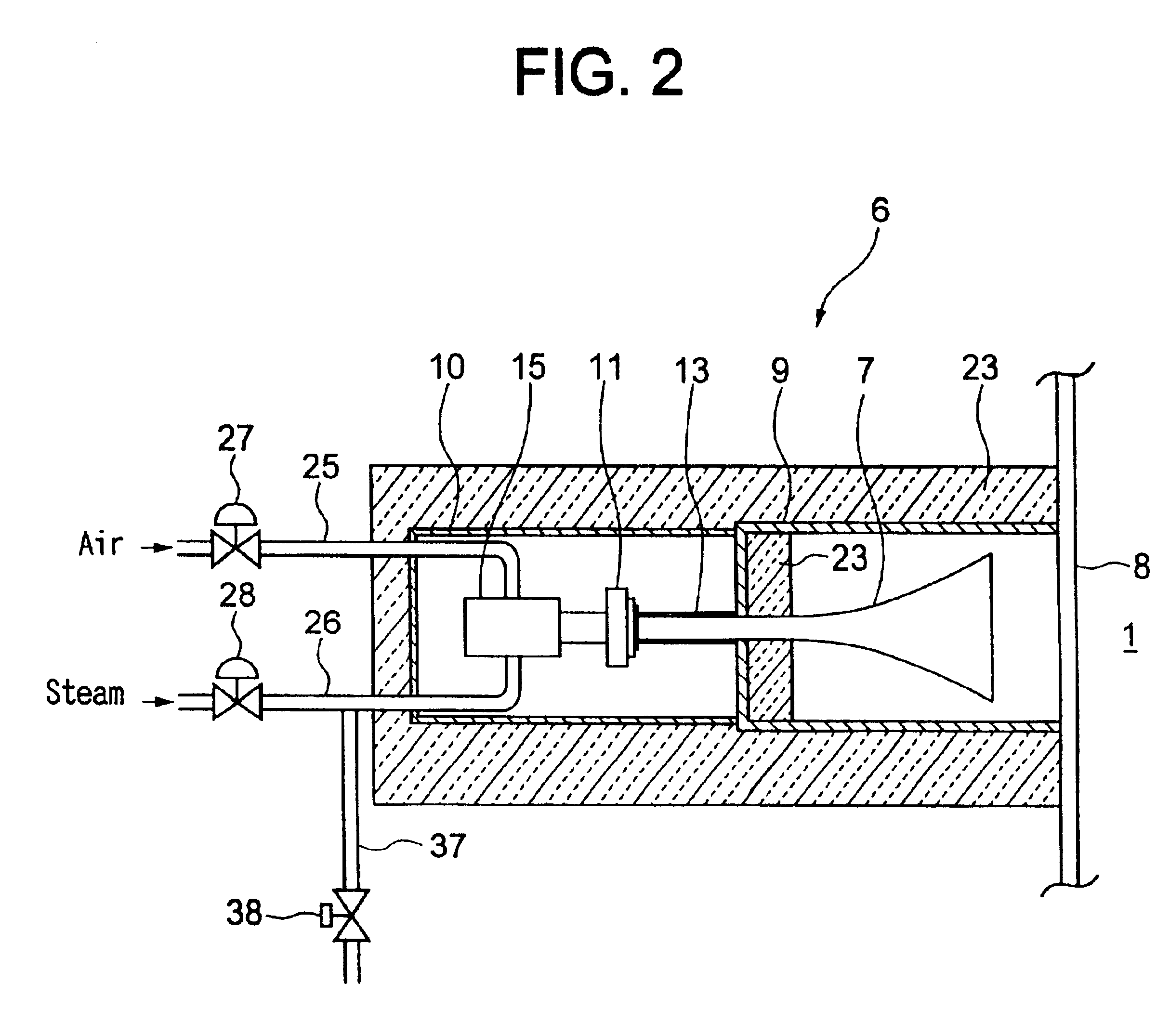
[0140]A description is given of embodiments of the sonic soot blower 6 of the above-described system (a) that varies the oscillation frequency in compliance with the operation conditions of...


PUM


Abstract

The sonic soot blower includes a sonic wave oscillator that oscillates sonic waves by compressed air or steam, a frequency-regulating portion that varies the frequencies of the sonic waves oscillated by the above-described sonic wave oscillator, a resonance tube that resonates the oscillated sonic waves, and a horn that amplifies the same, wherein powdery dust adhered to members installed inside a boiler furnace, etc., are removed, and are prevented from adhering to the above-described members. The above-described frequency-regulating portion is a gas mixer which is connected to the upstream side of the sonic wave oscillator and is provided with two or more gas conducting flow channels for conducting a compressive gas whose temperatures and/or densities are different from each other, or a slide mechanism that varies the length of the above-described resonance tube. Since the sonic soot blower is able to oscillate sonic waves while regulating the oscillation frequency so as to be suited to the operating conditions of the boiler, it becomes possible to effectively remove ash from the heat transmission tubes and to effectively prevent the same from adhering thereto over a wide range of operating conditions of soot blower-installed equipment (such as a boiler).

Description

[0001]This is a continuation of International Application PCT / JP01 / 00135, with an international filing date of Jan. 12, 2001 and now abandoned.TECHNICAL FIELD OF THE INVENTION[0002]The present invention relates to an acoustic (hereafter: sonic) soot blower in which a compressive gas is used as a drive source of sonic wave oscillation, and a method for operating the same. In particular, the invention pertains to a cleaning sonic soot blower that can remove, by sonically oscillating a gas body existing in the tubular member, powdery dust, etc., such as ash adhered to and accumulated at tubular members that are installed in soot blower-installed equipment such as a boiler, a combustion furnace, an incinerator, an independent superheater, an independent economizer, various types of heat exchangers, various types of plants, and / or various types of industrial apparatuses.[0003]Further, the sonic soot blower of the invention also functions to prevent powdery dusts, etc., such as ash from a...

Claims


Application Information

Patent Timeline
IPC IPC(8): F23J3/00F28G7/00F23J3/02F28G13/00
CPCF22B37/48F22B37/486F23J3/023F28G7/00F28G13/00
Inventor MATSUMOTO, TERUAKIYAMAGUCHI, RYOUSUKENISHIHARA, YASUO
Owner MITSUBISHI HITACHIPOWER SYST LTD
Why Eureka
Try Eureka