Semiconductor package with exposed die pad and body-locking leadframe

a technology of exposed die pads and semiconductors, applied in semiconductor devices, semiconductor/solid-state device details, electrical apparatus, etc., can solve the problems of difficult to reliably make wire bonds to them, relatively small and fragiledies, and large heat generation, so as to reduce the incidence of delamination and improve the mechanical locking effect, the effect of increasing the resistance of the package to penetration

a technology of exposed die pads and semiconductors, applied in semiconductor devices, semiconductor/solid-state device details, electrical apparatus, etc., can solve the problems of difficult to reliably make wire bonds to them, relatively small and fragiledies, and large heat generation, so as to reduce the incidence of delamination and improve the mechanical locking effect, the effect of increasing the resistance of the package to penetration

US6965157B1Inactive Publication Date: 2005-11-15AMKOR TECH SINGAPORE HLDG PTE LTD

Image

  • Semiconductor package with exposed die pad and body-locking leadframe
  • Semiconductor package with exposed die pad and body-locking leadframe
  • Semiconductor package with exposed die pad and body-locking leadframe

Examples


Embodiment Construction

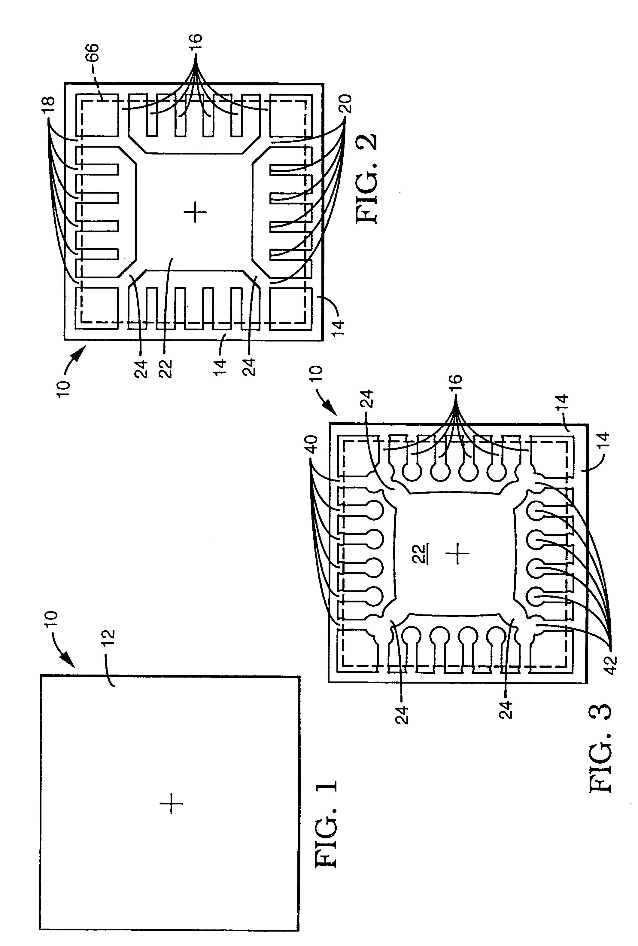
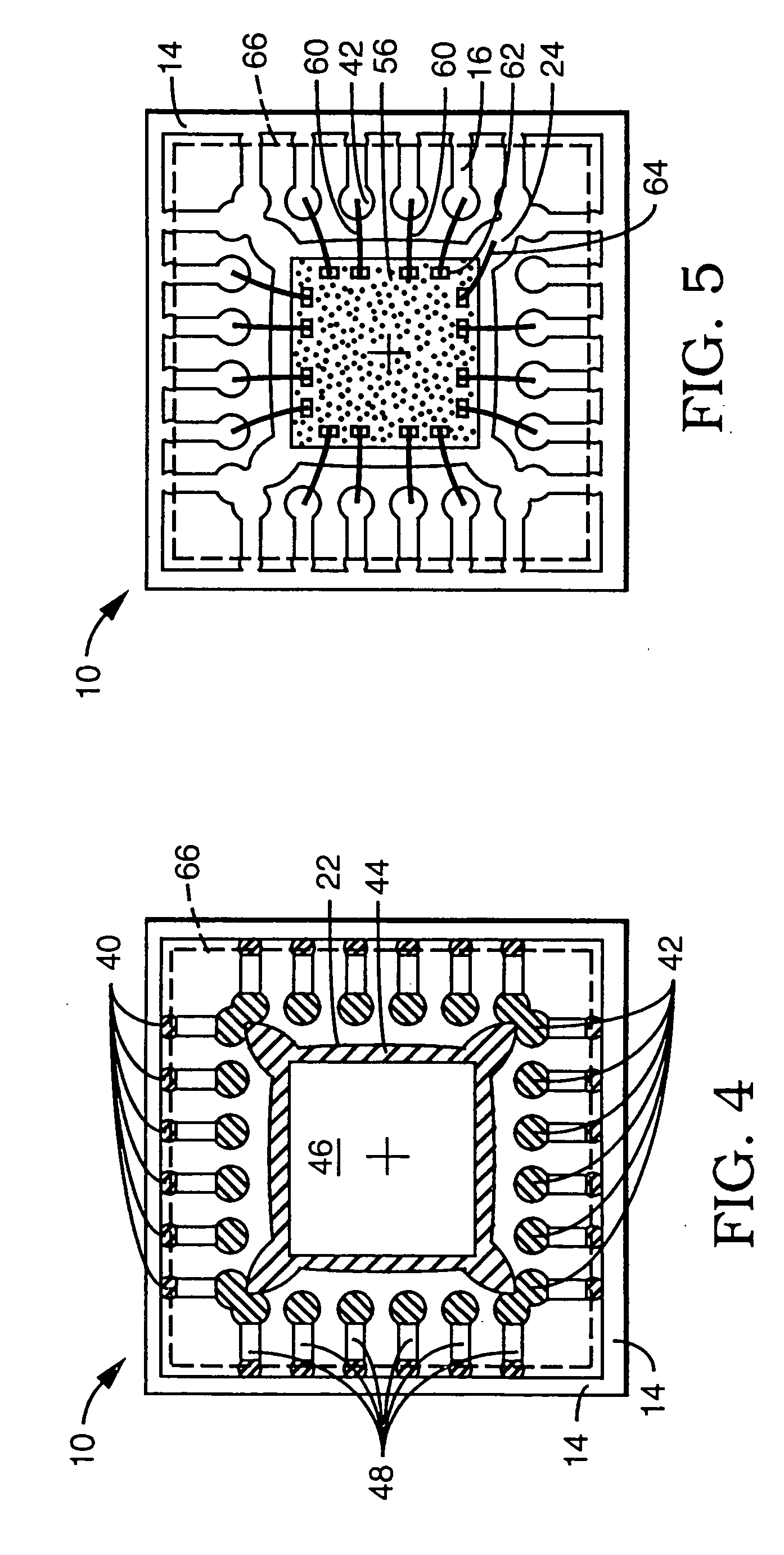
[0026]FIGS. 1–5 show in plan view the sequential fabrication and partial assembly of one embodiment of the novel leadframe 10 of the present invention. Fabrication of the leadframe begins with the provision of a thin, polygonal plate 12 of a ductile metal (FIG. 1), which is then patterned to form the nascent leadframe 10 (FIG. 2).

[0027]In the exemplary square embodiment illustrated in FIG. 1, the plate 12 is about 0.254 millimeters (β€œmm”) thick, about 4 mm on a side, and made of a copper alloy. Other metals suitable for use in the leadframe 10 include aluminum and iron-nickel (Kovar) alloys.

[0028]FIG. 2 is a top plan view of the leadframe 10 patterned from the plate 12 shown in FIG. 1. The leadframe 10 comprises a rectangular frame 14 defined around a periphery of the plate 12; a plurality of leads 16, each having an outer end portion 18 integral with the frame 14 and an inner end portion 20 extending toward a central region of the frame, the center of which is marked by a cross; an...


PUM


Abstract

A very thin, small outline, thermally enhanced semiconductor package includes a leadframe that is coined to form locking features on an exposed die pad and on a plurality of extremely narrow, closely spaced leads. The coined features improve the mechanical locking between the leadframe and the plastic body of the package to increase their resistance to delamination and subsequent penetration by moisture, and enable reliable wire bonds to be made to the otherwise extremely narrow leads.

Description

RELATED APPLICATION[0001]The present application is a continuation of U.S. application Ser. No. 09 / 436,158 entitled SEMICONDUCTOR PACKAGE WITH EXPOSED DIE PAD AND BODY-LOCKING LEADFRAME, filed Nov. 9, 1999 U.S. Pat. No. 6,847,103.BACKGROUND[0002]1. Field of the Invention[0003]This invention relates to packaging of semiconductors in general, and in particular, to a very thin, small outline, thermally enhanced semiconductor package having a coined leadframe that provides a die pad with an exposed surface and features that lock the leadframe more securely to the plastic body of the package.[0004]2. Description of the Related Art[0005]Integrated circuits (β€œICs”) are formed on a single die, or β€œchip,” cut from a semiconductor wafer containing a large number of identical dies. The dies are relatively small and fragile, are susceptible to harmful environmental elements, particularly moisture, and generate a relatively large amount of heat in a relatively small volume during operation. Acco...

Claims


Application Information

Patent Timeline
15 Nov 2005
Publication
US6965157B1
IPC
H01L21/48; H01L23/495; H01L23/48; H01L21/02; H01L23/28; H01L23/31
CPC
H01L21/4842; H01L23/49541; H01L23/49548; H01L23/3107; H01L2224/32245; H01L2224/48091; H01L2224/48247; H01L2224/48465
Inventors
PEREZ, ERASMO; ROMAN, DAVID T.