
Method and structure for selective thermal paste deposition and retention on integrated circuit chip modules

Inactive Publication Date: 2005-11-15
GLOBALFOUNDRIES INC
View PDF9 Cites 21 Cited by
  • Summary
  • Abstract
  • Description
  • Claims
  • Application Information

AI Technical Summary

Benefits of technology

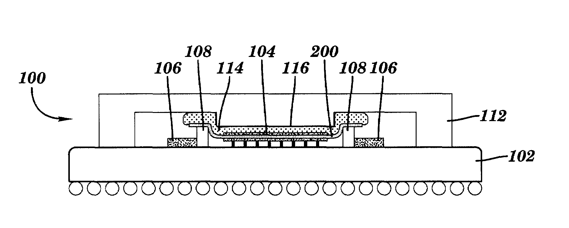
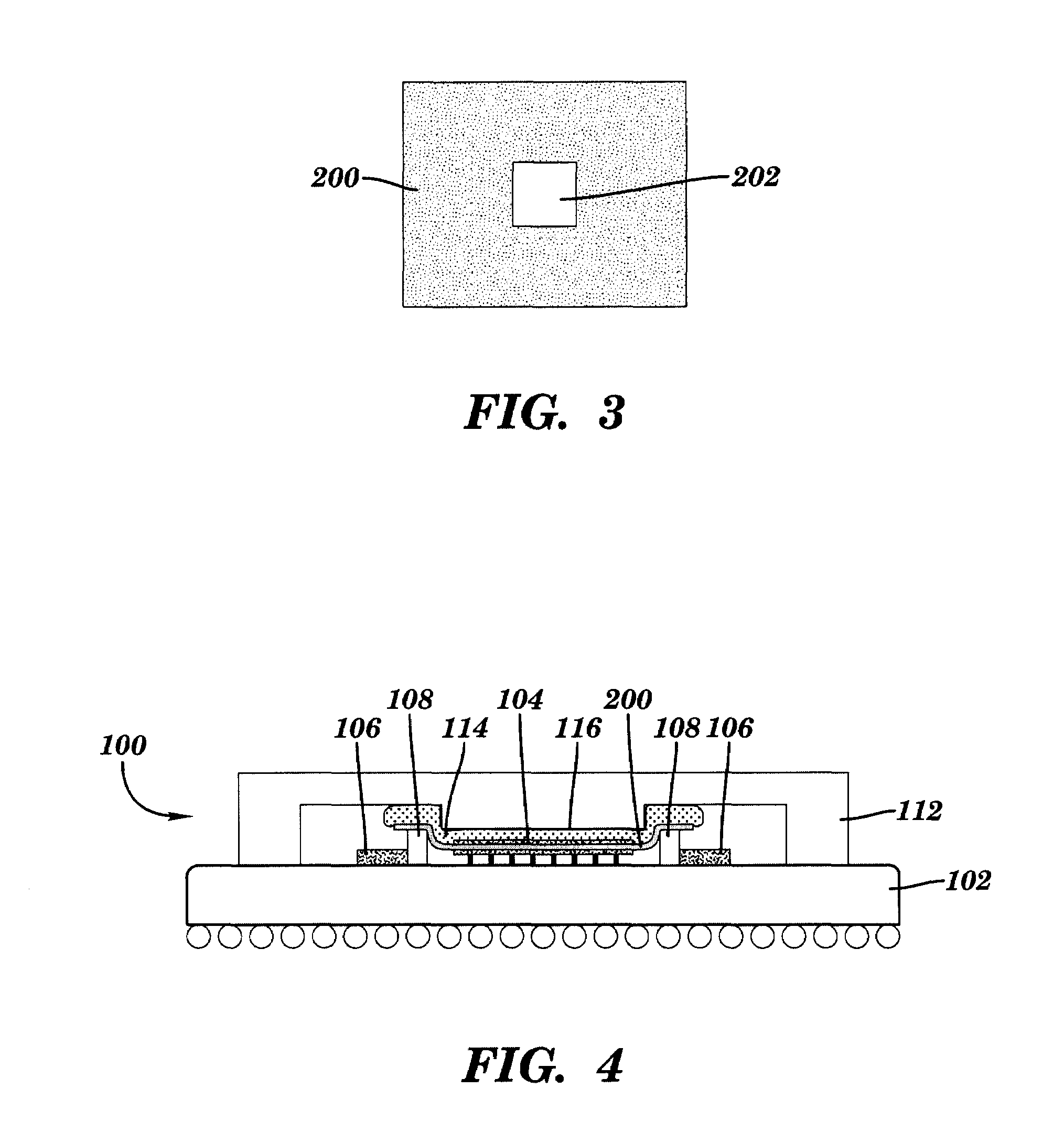
[0009]In another embodiment, an integrated circuit (IC) chip module includes at least one integrated circuit chip mounted upon a substrate, and a plurality of passive components mounted upon the substrate. A polymer based bib has at least one opening formed therein, the at least one opening configured to accommodate the at least one integrated circuit chip therein, and the bib further configured for attachment to one or more of the plurality of passive components. A protective cap is mounted over the at least one integrated circuit chip and attached to the substrate, wherein the bib is configured to retain thereon a thermally conductive paste initially applied to at least one of the integrated circuit chip and the protective cap.
[0010]In still another embodiment,

Problems solved by technology

The removal of heat from electronic components is a problem continuously faced by electronic packaging engineers.
As electronic components have become smaller and more densely packed on integrated boards and chips, designers and manufacturers now are faced with the challenge of how to dissipate the heat generated by these components.
It is well known than many electronic components, especially semiconductor components such as transistors and microprocessors, are more prone to failure or malfunction at high temperatures.
Thus, the ability to dissipate heat often is a limiting factor on the performance of the component.
For high power circuits (as well as smaller, more densely packed circuits of presently existing designs), however, simple air circulation often has been found to be insufficient to adequately cool the circuit components.
However, the thermal interface surfaces of an electronic component and associated heat sink are typically irregular, either on a gross or a microscopic scale.
These pockets reduce the overall surface area contact within the interface, which, in turn, reduces the efficiency of the heat transfer therethrough.
Moreover, as is also well known, air is a relatively poor thermal conductor.
Thus, the presence of air pockets within the interface reduces the rate of thermal transfer through the interface.
Unfortunately, the presence of thermal paste upon certain passive components can degrade the frequency response of analog as well as digital chip modules.
This in turn can have a negative effect on the module performance and cause the module not to meet designed electrical specifications.

Method used


Image

  • Method and structure for selective thermal paste deposition and retention on integrated circuit chip modules
  • Method and structure for selective thermal paste deposition and retention on integrated circuit chip modules
  • Method and structure for selective thermal paste deposition and retention on integrated circuit chip modules

Examples


Embodiment Construction

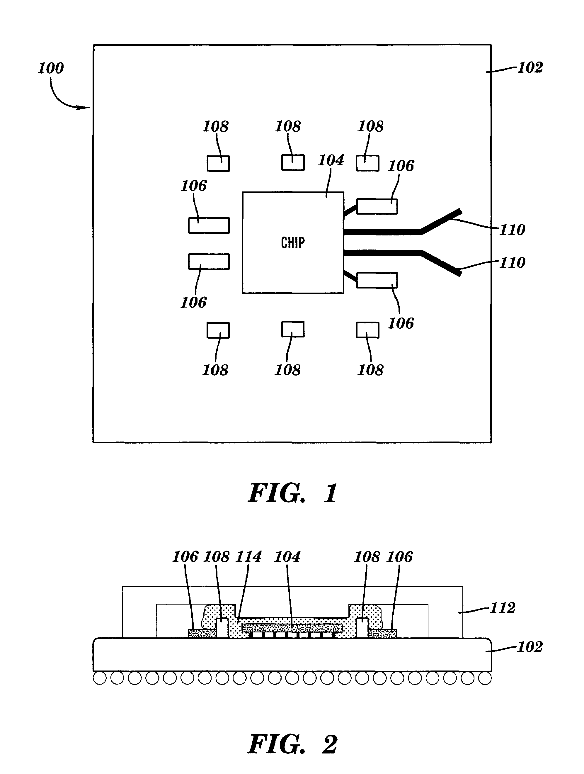
[0018]Referring initially to FIG. 1, there is shown a plan view of an exemplary integrated circuit chip module 100, suitable for use in accordance with an embodiment of the invention. The module 100 includes a substrate 102 having one or more integrated circuit (IC) chips 104 mounted thereon. In addition, a plurality of discrete, stand-alone electronic components are included on the substrate including, for example, surface mounted resistors 106, decoupling capacitors 108, and conductive microstrip traces 110. As shown in the cross-sectional view of FIG. 2, a metallic cap 112 or lid is attached to the surface of the substrate 102 for mechanically protecting the chip 104, and to provide a heat transfer path from the back of the chip 104 to the external cooling environment. In order to enhance heat transfer, a highly thermally conductive paste 114 containing ceramic, metal and / or metal oxide particles or the like (e.g., ATC 3.8) is applied between the back of the chip 104 and the cap ...


PUM


Abstract

An integrated circuit (IC) chip module includes at least one integrated circuit chip mounted upon a substrate, and a plurality of passive components mounted upon the substrate. A polymer based bib has at least one opening formed therein, the at least one opening configured to accommodate the at least one integrated circuit chip therein, and the bib further configured for attachment to one or more of the plurality of passive components. A protective cap is mounted over the at least one integrated circuit chip and attached to the substrate, wherein the bib is configured to retain thereon a thermally conductive paste initially applied to at least one of the integrated circuit chip and the protective cap.

Description

BACKGROUND OF INVENTION[0001]The present invention relates generally to semiconductor device packaging, and, more particularly, to a method and structure for selective thermal paste deposition and retention on integrated circuit chip modules.[0002]The removal of heat from electronic components is a problem continuously faced by electronic packaging engineers. As electronic components have become smaller and more densely packed on integrated boards and chips, designers and manufacturers now are faced with the challenge of how to dissipate the heat generated by these components. It is well known than many electronic components, especially semiconductor components such as transistors and microprocessors, are more prone to failure or malfunction at high temperatures. Thus, the ability to dissipate heat often is a limiting factor on the performance of the component.[0003]Electronic components within integrated circuits have been traditionally cooled via forced or natural convective circu...

Claims


Application Information

Patent Timeline
IPC IPC(8): H01L23/02H01L23/367
CPCH01L23/3675H01L23/3677H01L2924/3011H01L2224/16225H01L2224/73253H01L2924/15311
Inventor LEE, TIM H.LEI, CHON C.PAPAE, DONALD J.SZENHER, FRANCIS F.
Owner GLOBALFOUNDRIES INC
Learn More