Video input apparatus and image pickup system including the apparatus

Inactive Publication Date: 2005-11-15
CANON KK
View PDF32 Cites 48 Cited by
  • Summary
  • Abstract
  • Description
  • Claims
  • Application Information

AI Technical Summary

Benefits of technology

[0025]The present invention is made by noticing the above problems and its another object is to provide an image pickup system capable of properly operating a video input apparatus in accordance with the situation in a video telephone conference sy

Problems solved by technology

Therefore, the above conventional pickup apparatus has problems that the entire camera unit including the image processing unit must be replaced in order to improve, for example, the resolution of a video signa

Method used


Image

  • Video input apparatus and image pickup system including the apparatus
  • Video input apparatus and image pickup system including the apparatus
  • Video input apparatus and image pickup system including the apparatus

Examples


first embodiment

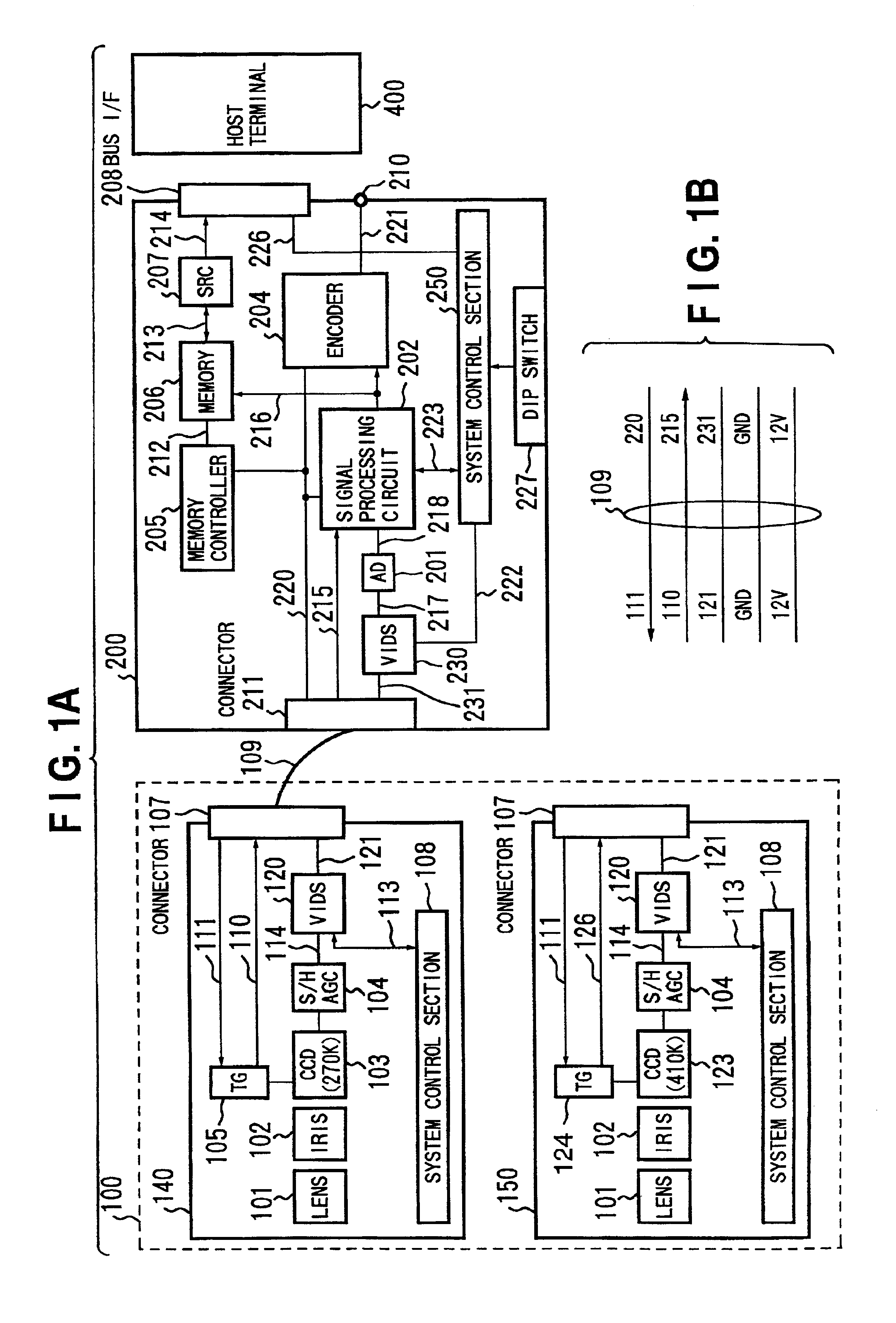
[0111]FIG. 1 is a block diagram showing the structure of the video input unit of the first embodiment of the present invention.

[0112]In FIG. 1, numeral 100 denotes a camera section, 200 denotes an image processing section formed like an extension board or extension card, 400 denotes a PC host terminal. The camera section 100 is connected with the image processing section 200 by, for example, a cable 109. The image processing section 200 is electrically connected by inserting a bus i / f (interface) 208 into the extension slot of the host terminal 400. The image processing section 200 and camera section 100 are controlled from the host terminal 400 via the bus i / f 208.

[0113]The camera section 100 can be exchangeable to the image processing section 200. Numeral 140 denotes a CCD camera having, for example, 270,000 pixels and 150 denotes a CCD camera having, for example, 410,000 pixels.

[0114]The structure of the CCD camera 140 is described below.

[0115]Numeral 108 denotes a system control...

second embodiment

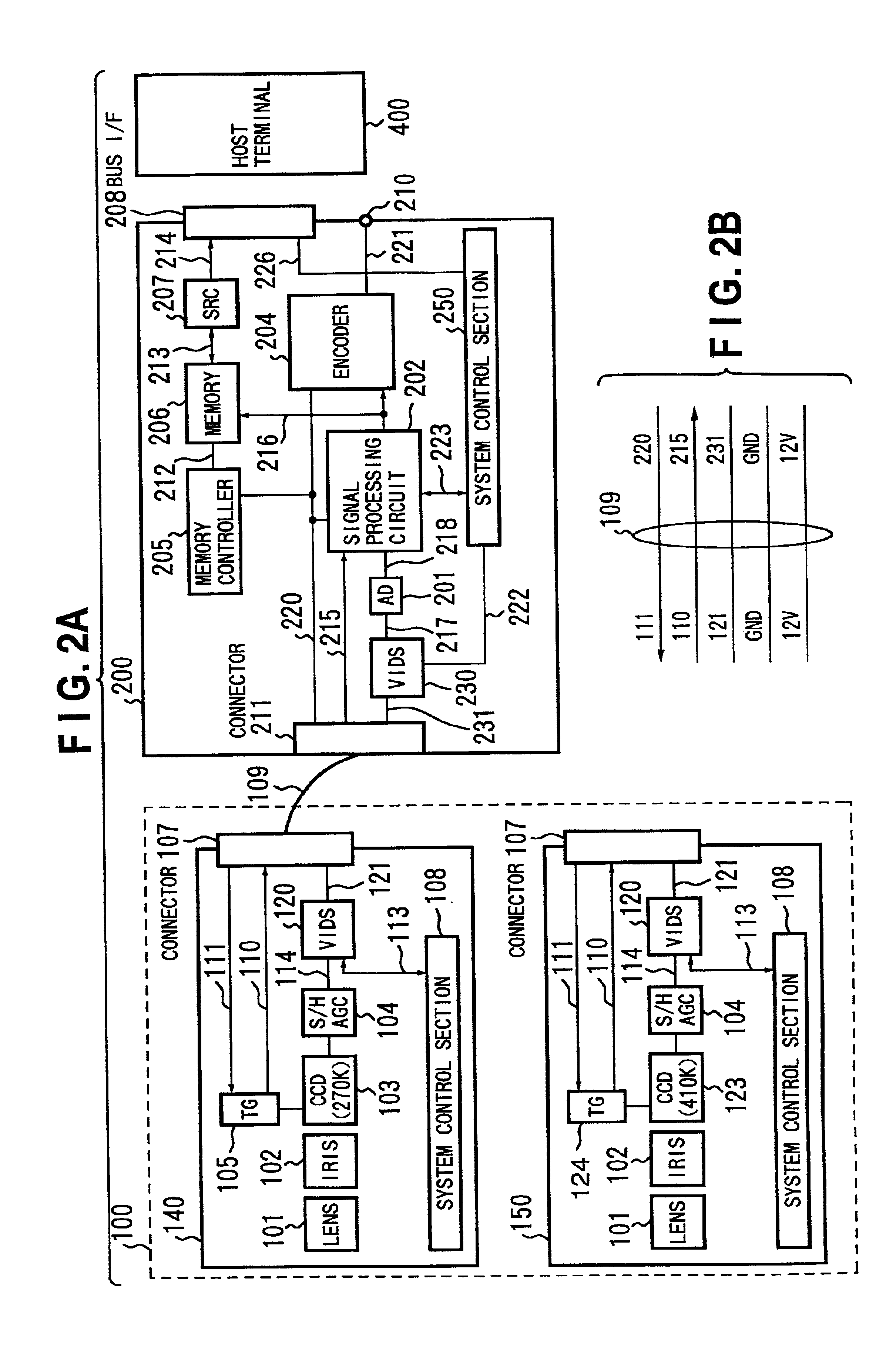
[0132]FIGS. 2A and 2B are block diagrams showing the structure of the video input unit which is the second embodiment of the present invention.

[0133]The second embodiment is different from the first embodiment in that the DIP switch 227 is not used. The system control section 250 does not detect the type of camera of the camera section 100 by reading the set value of the DIP switch 227 but it detects the type of camera by using a synchronizing signal supplied from the camera section 100. In the case of the second embodiment, it is detected whether the camera of the camera section 100 is the 270,000-pixel CCD camera or 410,000-pixel CCD camera by using a video clock sent to the image processing section 200.

[0134]FIG. 3 is a block diagram showing the structure of the system control section 250 of the image processing section 200. The system control section 250 includes a one-chip microcomputer and software for controlling the microcomputer. Numeral 251 denotes an internal bus, 252 den...

third embodiment

[0150]The third embodiment of the present invention is described below.

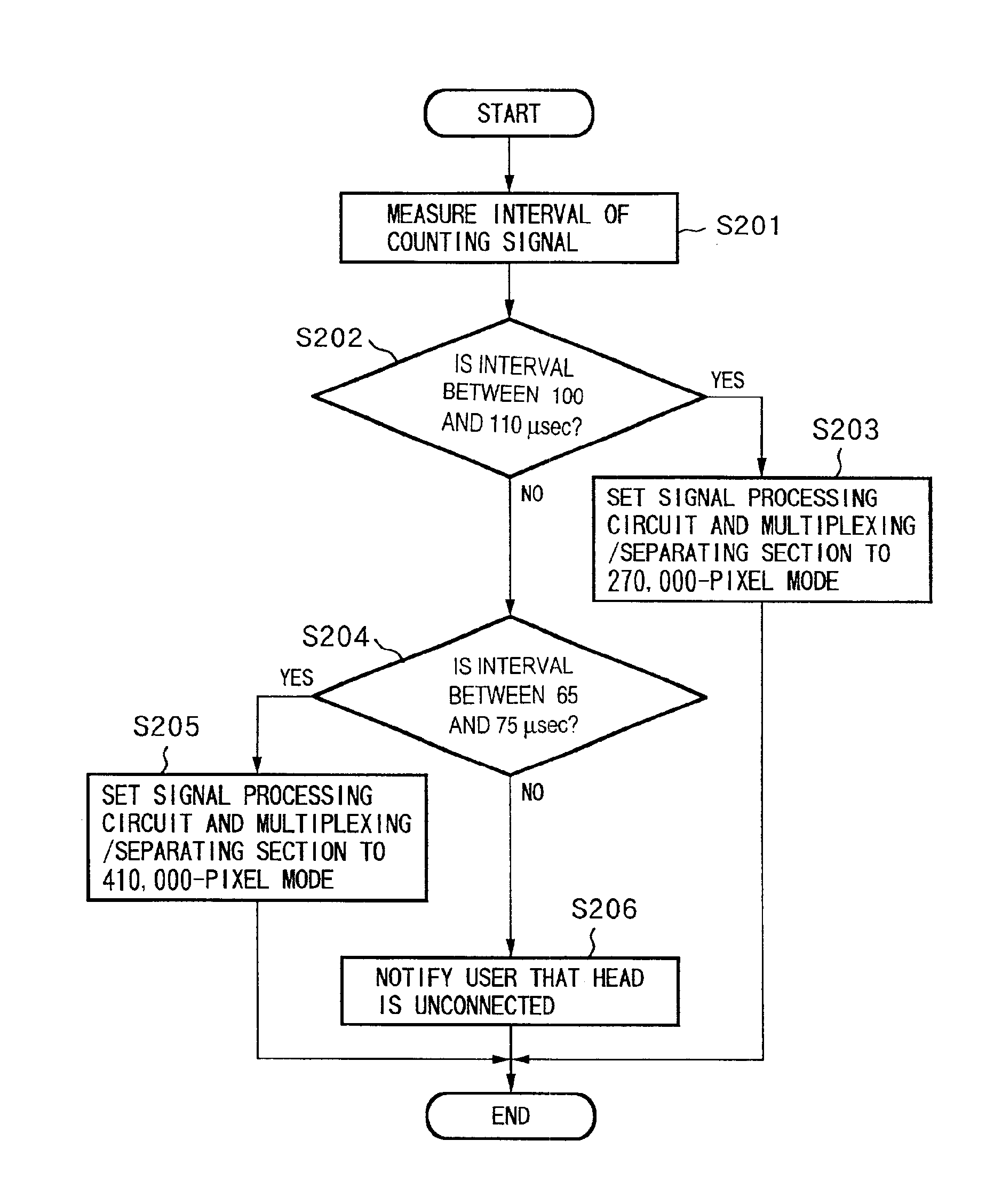
[0151]When the signal processing circuit 202 is not used, it is also possible to use a counter circuit for counting the pulses of the video clocks 215 and use the pulses output from the counter circuit for decision.

[0152]FIG. 9 is an illustration showing an example in which a counter circuit 240 is connected to the system control section 250 in order to detect a type of camera of the camera section 100. The counter circuit 240 counts video clocks 215. When the circuit 240 completes counting of the video clocks 215 in a predetermined time period, it notifies the system control section 250 by adding a pulse to a signal 233.

[0153]For example, if a value counted by the counter circuit 240 in the predetermined time period becomes less than “1,000”, then it is determined that the 270,000-pixel CCD camera 140 is connected. In this case, a 9.5-MHz video clock 215 is input, a pulse is generated every 105 s. On the other h...


PUM


Abstract

A video input apparatus and image pickup system having a camera section having a camera unit, and a video processing section for processing an image signal from the camera section so as to supply to a host terminal. The camera section outputs a multiplexed signal on which synchronizing signals of an image signal are multiplexed on the image signal, to the video processing section through a cable. The video processing section separates the image signal and the synchronizing signals from the multiplexed signal and processes the image signal to output a video signal. The camera unit in the camera section is exchangeable, and the video processing section detects the type of the camera unit based on the separated synchronizing signals and processes the image signal in accordance with the detected type of the camera unit.

Description

BACKGROUND OF THE INVENTION[0001]The present invention relates to an image pickup system for transmitting image information, particularly to a video input apparatus and an image pickup system including the video input apparatus preferably used to a video telephone conference system for transferring images, voices and other multimedia information between remote points through a general public telephone network.[0002]A conventional image pickup apparatus is constituted so as to mount a zooming or auto-focusing camera unit on a pan tilting head such as a tripod head, process a picked-up video signal by an image processing unit set in the camera unit, output the processed video signal in accordance with an NTSC signal format, and display the signal on a monitor or transmit the signal to a host terminal of a personal computer or the like.[0003]Therefore, the above conventional pickup apparatus has problems that the entire camera unit including the image processing unit must be replaced i...

Claims


Application Information

Patent Timeline
IPC IPC(8): H04N7/14H04N5/232
CPCH04N5/232H04N7/142H04N7/148H04N23/665
Inventor HABA, YOSHITOITO, KANMIYASAKA, ICHIKO
Owner CANON KK
Why Eureka
Try Eureka