Vehicle measuring apparatus and method for toll collection system

a technology for toll collection and vehicle measurement, applied in the field of toll collection system, can solve the problems of inability to distinguish between toll paid vehicles and non-paid vehicles, inability to measure vehicles travelling faster than a certain speed, and inability to use a vehicle type classification and toll collection system, etc., to achieve accurate detection of vehicles

Inactive Publication Date: 2005-11-15
JIN WOO IND
View PDF7 Cites 25 Cited by
  • Summary
  • Abstract
  • Description
  • Claims
  • Application Information

AI Technical Summary

Benefits of technology

[0045]Therefore, an object of the present invention is to provide vehicle measuring apparatus and method that are capable of accurately detecting a vehicle by using a laser sensor.

Problems solved by technology

However, with only the wireless communication, there is no way to discriminate a toll paid vehicle and a non-paid vehicle.
However, with the conventional contact type vehicle measuring apparatus using the tread-board, it is impossible to measure a vehicle travelling faster than a certain velocity.
However, the non-contact type vehicle measuring apparatus using the photo sensor does not possibly measure a height or a width of the vehicle but sense only the entry of a vehicle, and as such, it is not usable for a vehicle type classification and toll collection system.
However, this non-contact type vehicle measuring apparatus has problems that its accuracy in measurement can be severely degraded if the detection line 222 is damaged or light scatters due to rain or snow.
However, the vehicle measuring apparatus using CCD camera 331 has problems that it can not obtain accurately an image of the vehicle and thus cause a serious measurement error if the intermittent marking pattern 312 is damaged or the amount of light reflected from the intermittent marking pattern 312 changes due to clouds.
Nevertheless, the vehicle measuring apparatus using the laser beam has the following problems.
Therefore, conversion of the width of vehicle to length by using information of angle and height may cause much error.

Method used


Image

  • Vehicle measuring apparatus and method for toll collection system
  • Vehicle measuring apparatus and method for toll collection system
  • Vehicle measuring apparatus and method for toll collection system

Examples


first embodiment

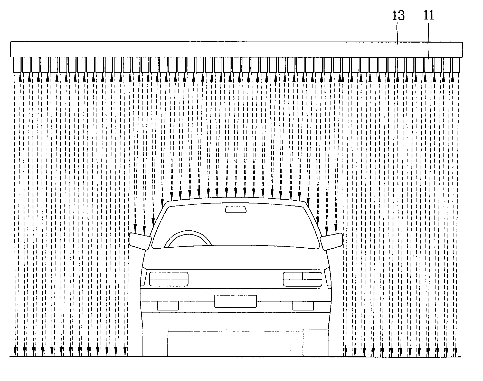
[0079]FIG. 8 is a schematic view showing an installation state of a vehicle measuring apparatus in accordance with the present invention.

[0080]As shown in FIG. 8, the vehicle measuring apparatus includes a plurality of laser sensors 11 installed to be close to each other corresponding to the width of the whole roadway on a gantry 13 separated from the road surface with a predetermined height, and a processor means 12 electrically connected to the plurality of laser sensors 11 to operate the plurality of laser sensors 11 and calculating height and width of a vehicle travelling at a high speed on the basis of a signal for vehicle measurement outputted from the laser sensor 11 and previously stored installation information of the plurality of laser sensors.

[0081]Reference numerals 14 and 15 designate vehicles running on the multi-lane road.

[0082]The gantry 13 is a means for supporting and separating the plurality of laser sensors from the ground of the road with a predetermined height....

second embodiment

[0146]In the present invention, in operating simultaneously different groups of laser sensors after grouping laser sensors which are within the maximum distance in which an interference is made to each other, the laser sensors in the same group are sequentially operated, so that a high speed processing is possible.

[0147]The vehicle measuring apparatus in accordance with the second embodiment of the present invention will now be described with reference to FIG. 18.

[0148]FIG. 18 illustrates a major part of a vehicle measuring apparatus in accordance with the second embodiment of the present invention.

[0149]With reference to FIG. 18, the vehicle measuring apparatus in accordance with the second embodiment of the present invention comprises ‘m’ number of laser sensor groups 101-1˜101-m for grouping ‘n’ number of laser sensors corresponding to entire roadway width; a multiplexer unit 102 for outputting a pulse signal for sequentially driving laser sensors in the same group while driving ...


PUM


Abstract

Vehicle measuring apparatus and method are disclosed to accurately measure height and width of a vehicle moving at a high speed. The vehicle measuring apparatus includes: a plurality of laser sensors separated from the road surface with a predetermined height and installed closely to each other corresponding to width of every roadway on the road, and receiving a reflection light of a laser light emitted onto the road from the plurality of the laser sensors and outputting a vehicle measurement signal; and a processor means electrically connected to the laser sensors and calculating height and width of the vehicle on the basis of the signal to measure the vehicle and previously stored installation information of the plurality of laser sensors.

Description

BACKGROUND OF THE INVENTION[0001]1. Field of the Invention[0002]The present invention relates to a toll collection system in a toll road for vehicles and, more particularly, to a vehicle measuring apparatus using a laser sensor suitably applied to the system.[0003]2. Description of the Background Art[0004]Recently, attempts to introduce an intelligent traffic system are being made throughout the world. For example, an electronic toll collection system (abbreviated as ETCS), an automatic toll collection system is being introduced which is capable of reducing product delivery cost and an environment pollution through mitigation of vehicle congestion in tollgate as occurring in the current manual Toll Collection System (abbreviated as TCS), and reducing operation and maintenance cost and improving a service through a toll collecting automation.[0005]The electronic toll collection system is collecting a toll by using a Dedicated Small Region Communication (abbreviated as DSRC) wirelessl...

Claims


Application Information

Patent Timeline
Patent Type & Authority Patents(United States)
IPC IPC(8): G07B15/00G08G1/015G08G1/04G07B15/06G08G1/017
CPCG07B15/06G08G1/015G08G1/04G08G1/017
Inventor LEE, SANG-JEANSONG, IN-JUNELIM, DAE-WOONJUN, JOON-SUK
Owner JIN WOO IND
Why Eureka
Try Eureka