
Integrated lead suspension for high density drive

a lead suspension and high density technology, applied in the field of head suspension assembly, can solve the problems of slipping away from the load beam, limiter in prior, manufacturing difficulties, etc., and achieve the effect of preventing damage to the insulating layer, improving the dynamic performance of the suspension assembly, and facilitating laser solder ball bonding of the pads

Inactive Publication Date: 2005-11-15
WESTERN DIGITAL TECH INC
View PDF47 Cites 37 Cited by
  • Summary
  • Abstract
  • Description
  • Claims
  • Application Information

AI Technical Summary

Benefits of technology

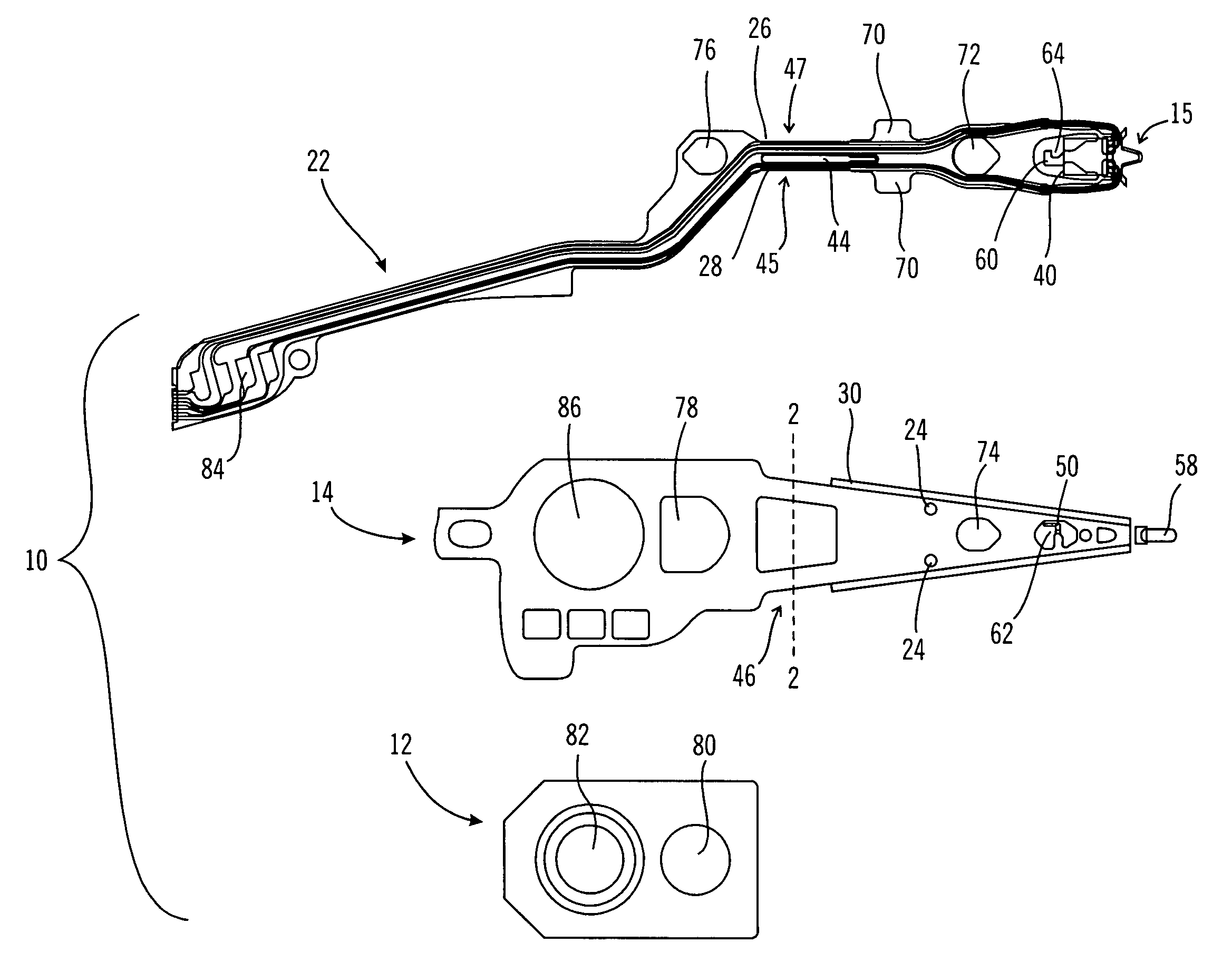
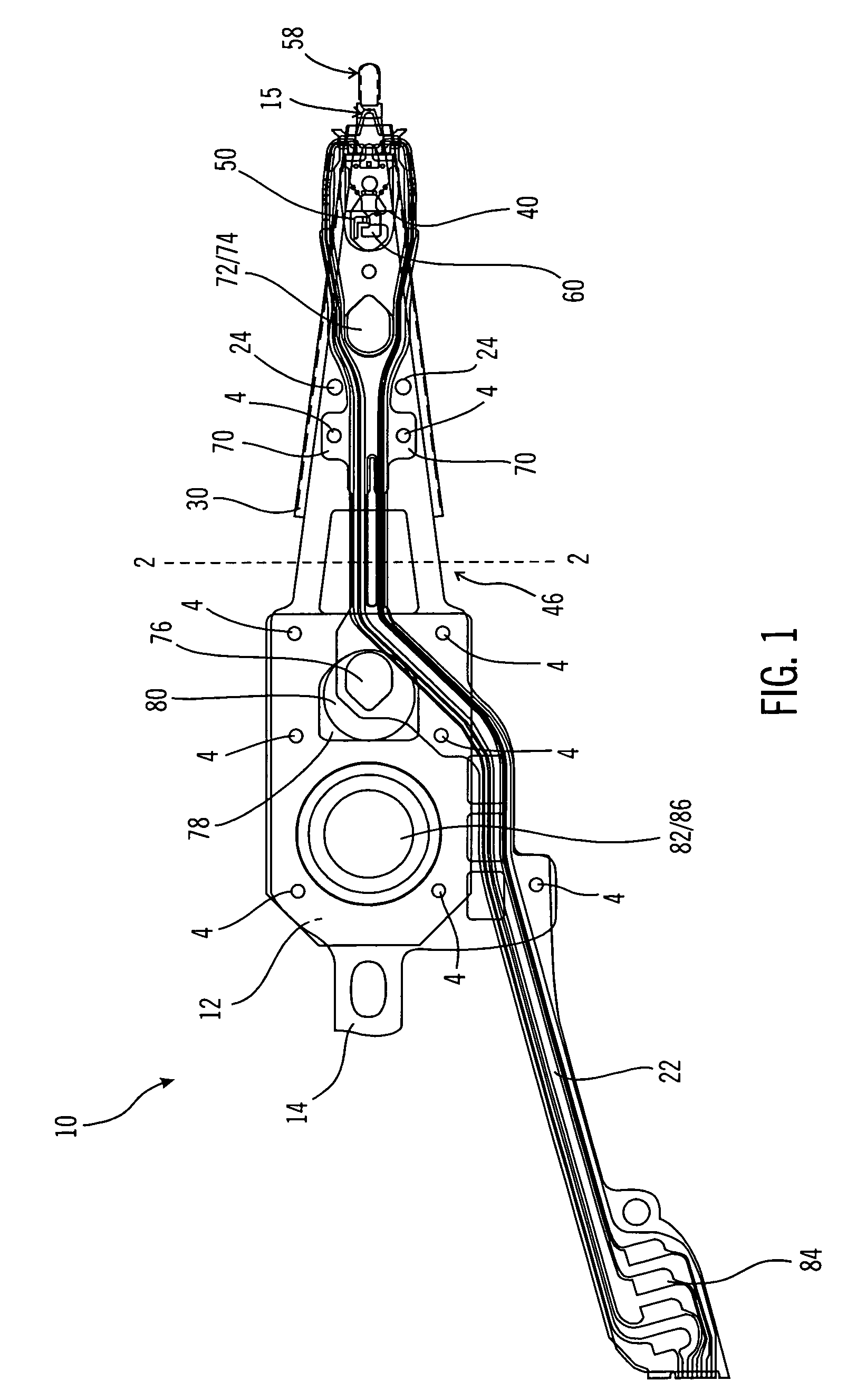
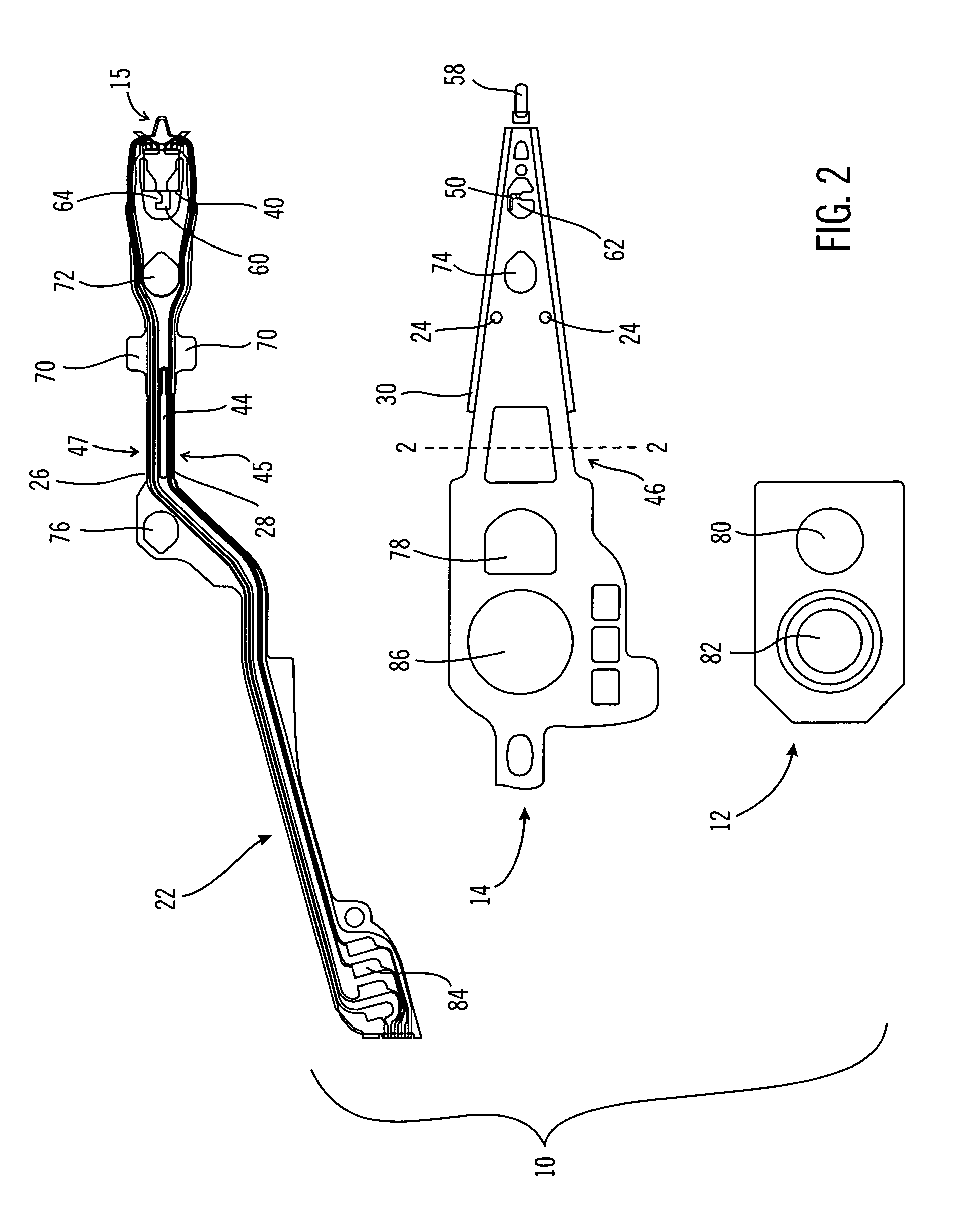
[0010]The integrated lead suspension assembly design of the present invention overcomes many of the drawbacks in the prior art. In accordance with one aspect of the present invention, a solder ball bonding technique is applied to bond the electrical traces to a slider. A novel configuration of the terminating pads for the electrical traces and the adjacent insulation layer on the flexure assembly facilitates laser solder ball bonding of the pads to the read / write terminal contacts on the slider. The pads are oversized with respect to the insulation layer to prevent damage to the insulating layer during laser bonding process. Laser solder ball bonding process does not require clamping of the components through the tip region of the load beam. Consequently, the tip of the load beam can be made narrow while providing a structure permitting head loading and unloading functions, which improves the dynamic performance of the suspension assembly.
[0012]In accordance with another aspect of the present invention, the flexure assembly is configured such that it requires no permanent bending (as opposed to flexing) in its forming process, and any permanent bending required is done to the load beam. This improves better tolerance control in view of the flat structure. This also simplifies processing, since the flexure assembly comprises thinner and more delicate components of traces, insulation and backing layer, which are more difficult to be accurately bent and handled. In another aspect of the present invention, the limiter that limits the travel of the flexure assembly is formed on the load beam and it is bent to the functional position only after attachment of the flexure assembly to the load beam.
[0014]Low profile flanges are provided along the edges of the load beam to optimize bending stiffness and flow induced vibration. In accordance with one embodiment of the present invention, a 30°–60° bend from the plane of the load beam would provide improved dynamic characteristics. Dimples may be provided along the load beam to facilitate insertion of a plastic head separation tool.

Problems solved by technology

However, the external excitation acting upon the wide load beam results in torsional (off track) and in-plane bending modes that are at lower resonance frequencies during operation of the disk drive, which are undesirable as they affect the dynamic performance of the drive.
However, because of the relative location of the slider and the limiter, the limiter in prior art is known to slide away from the load beam during high shock in the unloaded position.
The steps required for this structure create difficulties in manufacturing.

Method used


Image

  • Integrated lead suspension for high density drive
  • Integrated lead suspension for high density drive
  • Integrated lead suspension for high density drive

Examples


Embodiment Construction

[0027]This invention is described in a preferred embodiment in the following description with reference to the figures. While this invention is described in terms of the best mode for achieving this invention's objectives, it will be appreciated by those skilled in the art that variations may be accomplished in view of these teachings without deviating from the spirit or scope of the invention.

[0028]Referring now to FIG. 10, there is shown a disk drive 120 embodying the suspension of the present invention. As shown in FIG. 10, at least one rotatable magnetic disk 122 is supported on a spindle 126 and rotated by a disk drive motor 130. The magnetic recording media on each disk is in the form of an annular pattern of concentric data tracks (not shown) on the disk 122.

[0029]At least one slider 124 is positioned on the disk 122, each slider 124 supporting one or more magnetic read / write heads 134. As the disks rotate, the slider 124 is moved radially in and out over the disk surface 136...


PUM

PropertyMeasurementUnit
flexibleaaaaaaaaaa
areaaaaaaaaaaa
structural rigidityaaaaaaaaaa

Abstract

The integrated lead suspension assembly comprises several improvements. An oversized terminating pad for the electrical traces and a smaller adjacent insulation layer on the flexure assembly enable laser solder ball bonding of the pads to the read / write terminal contacts on the slider without clamping operation. Consequently, the tip of the load beam can be made narrow for a structure that provides for head loading and unloading functions, which improves the dynamic performance of the suspension assembly. The flexure assembly is configured such that it requires no permanent bending in its forming process, and any permanent bending required is done to the load beam. The limiter that limits the travel of the flexure assembly is formed on the load beam and it is bent to the functional position only after attachment of the flexure assembly to the load beam. The limiter is configured and positioned at the leading edge side of the slider to optimize the unloading process and to minimize the possibility of disengagement of the limiter and the flexure assembly during high shock environment. Asymmetric backing branches are provided for the read and write traces in the flexure assembly located at the hinge area of the load beam, the widths of which are sized to optimize the dynamic signal performance of the read and write traces without impact on the vertical stiffness of the suspension. Low profile flanges at 30°–60° that bend from the plane of the load beam are provided along the edges of the load beam to optimize bending stiffness and flow induced vibration. Dimples are provided along the load beam to facilitate insertion of a plastic head separation tool.

Description

BACKGROUND OF THE INVENTION[0001]1. Field of the Invention[0002]This invention relates generally to magnetic disk storage systems, and more particularly, to a head suspension assembly for use in a magnetic disk storage system.[0003]2. Description of Related Art[0004]Magnetic disk drives are information storage devices that utilize at least one rotatable magnetic media disk having concentric data tracks defined for storing data, a magnetic recording head or transducer for reading data from and / or writing data to the various data tracks, a slider for supporting the transducer in proximity to the data-tracks typically in a flying mode above the storage media, a suspension assembly for resiliently supporting the slider and the transducer over the data tracks, and a positioning actuator coupled to the transducer / slider / suspension combination for moving the transducer across the media to the desired data track and for maintaining the transducer over the data track center line during a rea...

Claims


Application Information

Patent Timeline
Patent Type & Authority Patents(United States)
IPC IPC(8): G11B5/48
CPCG11B5/484G11B5/486Y10T29/49025Y10T29/49027Y10T29/49144Y10T29/49028Y10T29/49155
Inventor PAN, TZONG-SHII S.PATTANAIK, SURYA
Owner WESTERN DIGITAL TECH INC
Learn More