System, device and method for providing voltage regulation to a microelectronic device

a microelectronic device and voltage regulation technology, applied in the field of power regulation systems, can solve the problems of increasing the demand on the operation voltage decreases, and the frequency of the increase of the power regulation system, and achieves the effect of rapid active transient response and high-speed signal settling capabilities

Inactive Publication Date: 2005-11-15
INFINEON TECH AUSTRIA AG
View PDF9 Cites 149 Cited by
  • Summary
  • Abstract
  • Description
  • Claims
  • Application Information

AI Technical Summary

Benefits of technology

[0011]The present invention overcomes the problems outlined above and provides an improved power regulation system, device and method. In particular, the present invention provides a power regulation system and device with ...

Problems solved by technology

As the speed and integration of microprocessors increase, the demands on the power regulation system increases.
In particular, as gate counts increase, the power regulation current demand increases, the operating voltage decreases and transient events (e.g., relatively large voltage spikes or droops at the load) typically increase in both magnitude and frequency.
Such a droop or spike is problematic because it may cause the device to lock up or otherwise fail.
Often, AVP is unable to overcome the third droop/spike entirely due to the magnitude of the current change.
However, as the microprocessor clock speed increases and the board area available for bulk capacitors decreases, the second and third droops are becoming more prominent and the prior art SPC's are less able to compensate ...

Method used


Image

  • System, device and method for providing voltage regulation to a microelectronic device
  • System, device and method for providing voltage regulation to a microelectronic device
  • System, device and method for providing voltage regulation to a microelectronic device

Examples


Embodiment Construction

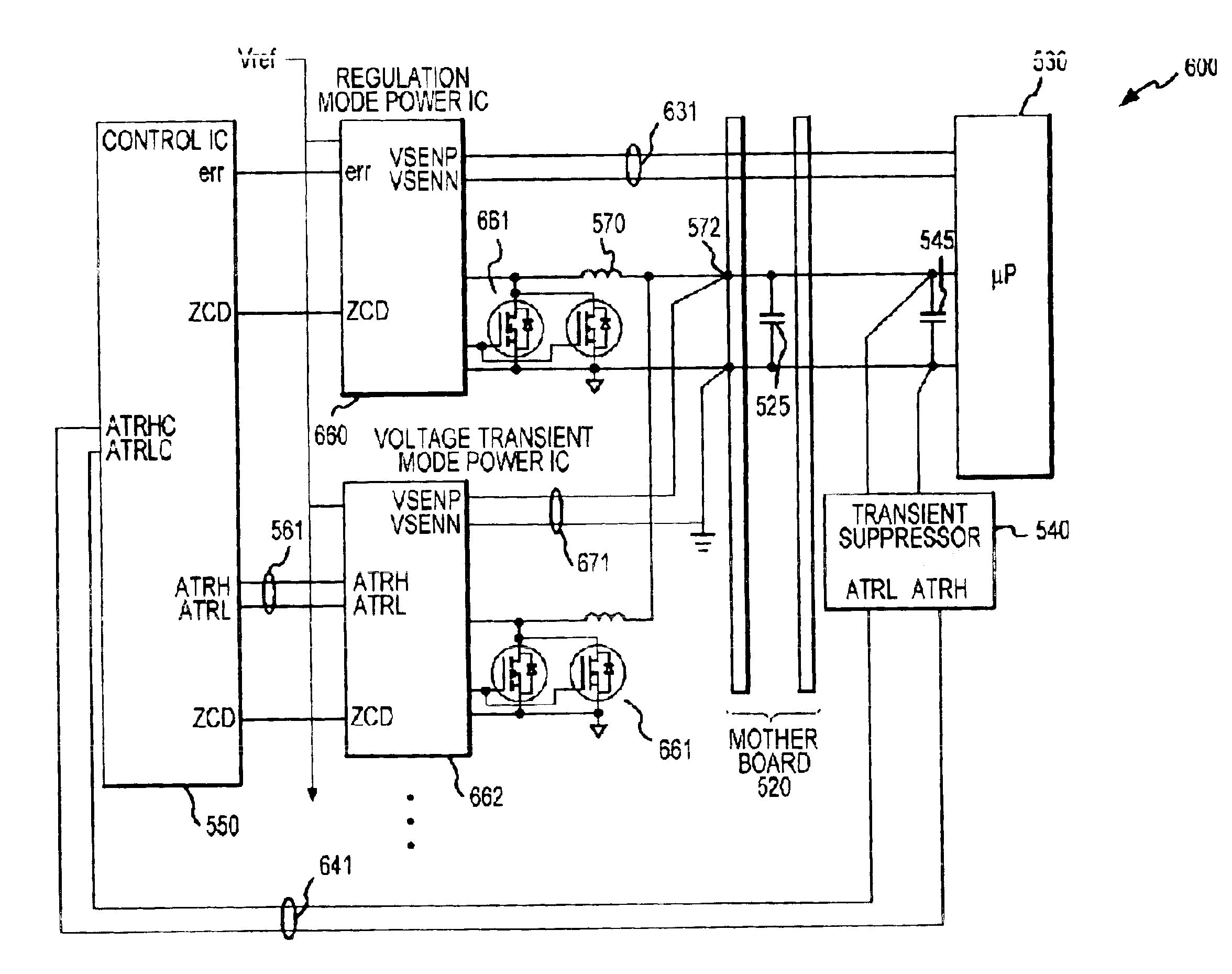
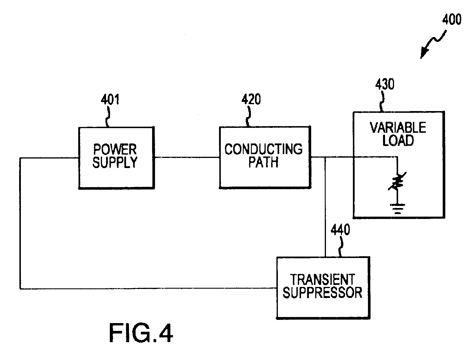
[0030]The present invention relates to an improved power regulation system or power conversion system suitable for providing regulated power to a microelectronic device. Although the power converter disclosed herein may be conveniently described with reference to a single or multiphase buck converter system, it should be appreciated and understood by one skilled in the art that any switching power converter or regulator topology may be employed, e.g., buck, boost, buck-boost, flyback, or the like. Further, although the power regulator, system, and method of the present invention may be used to supply power to any microelectronic device, the invention is conveniently described herein with reference to supplying power to a microprocessor.

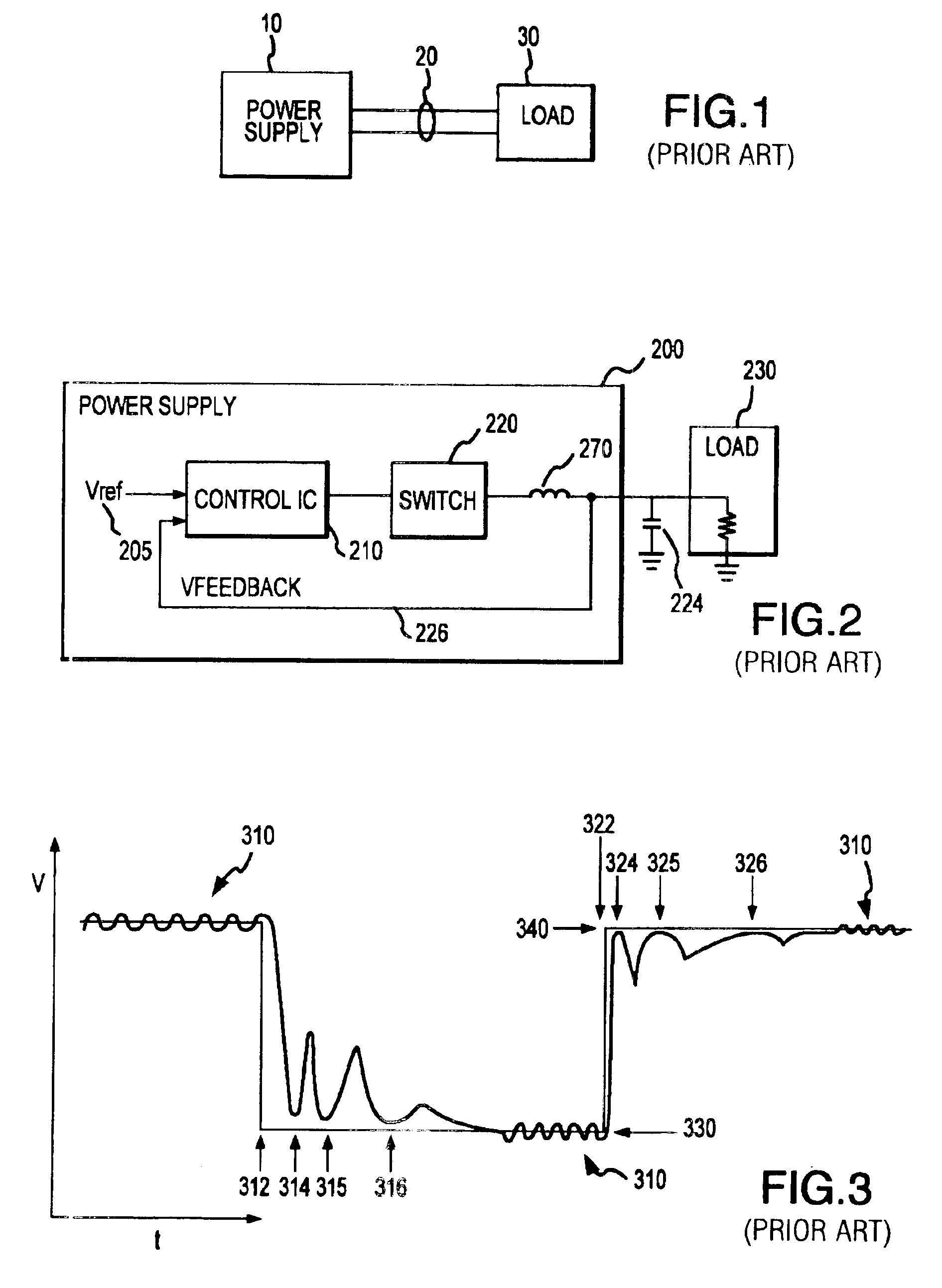
[0031]As discussed above, efforts by others have generally failed to develop a SPC capable of addressing first, and to some extent second and third droops and spikes which result from transient load activity. The present invention overcomes the proble...


PUM


Abstract

The present invention provides a power regulation system and method with high speed signal settling capabilities for providing rapid active transient response to a microelectronic device. An active transient response system includes a power supply configured to receive external and/or internal signals indicating the occurrence of transient load conditions and to respond to the transient load conditions based on one or more of these signals. The system may further include a transient suppressor configured for early detection of transients, assisting in transient suppression, and early signaling of transient activity to the power supply.
The system provides rapid recovery to steady state operation from the active transient response mode by using a digital compensator to quickly modifying the duty cycle and provide a voltage offset proportional to the transient microprocessor load step. Recovery is further improved by current rephasing techniques.

Description

CROSS REFERENCE TO RELATED APPLICATIONS[0001]This application includes subject matter that is related to and claims priority from the following U.S. Utility patent applications: Ser. No. 09 / 771,756 (filed Jan. 29, 2001 and entitled “Apparatus for Providing Regulated Power to an Integrated Circuit”), Ser. No. 09 / 944,417 (filed Aug. 31, 2001 and entitled “Wide Band Regulator with Fast Transient Suppression Circuitry”), Ser. No. 09 / 945,187 (filed Aug. 31, 2001 and entitled “Apparatus and System for Providing Transient Suppression Power Regulation”), Ser. No. 09 / 975,195 (filed Oct. 10, 2001 and entitled “System and Method for Highly Phased Power Regulation”), Ser. No. 09 / 978,296 (filed Oct. 15, 2001 and entitled “System and Method for Current Sensing”), Ser. No. 09 / 978,125 (filed Oct. 15, 2001 and entitled “System and Method for Detection of Zero Current Condition”), and Ser. No. 09 / 978,294 (filed Oct. 15, 2001 and entitled “System and Method for Highly Phased Power Regulation Using Ada...

Claims


Application Information

Patent Timeline
IPC IPC(8): G06F1/30
CPCG06F1/305
Inventor DUFFY, THOMAS P.GOODFELLOW, RYANTRIVEDI, MALAYMORI, KEVINTANG, BENJAMIM
Owner INFINEON TECH AUSTRIA AG
Why Eureka
Try Eureka