Dynamic pressure bearing device, and manufacturing method and assembly jig thereof

a technology of dynamic pressure bearing and manufacturing method, which is applied in the direction of sliding contact bearings, recording information storage, instruments, etc., can solve the problems of difficult control of the width dimension of the gap in the dynamic pressure bearing portion, especially the gap in the thrust bearing portion, within the desired range, and the difficulty of ensuring the dimension precision of these constituent parts in view of the precision of parts, so as to achieve the effect of enhancing product precision

Inactive Publication Date: 2005-11-22
RELIAL CORP
View PDF10 Cites 9 Cited by
  • Summary
  • Abstract
  • Description
  • Claims
  • Application Information

AI Technical Summary

Benefits of technology

[0088]When the assembly jig as described above is thus used in carrying out the aforesaid manufacturing methods of the dynamic pressure bearing device of the present invention, the pressure can be applied evenly to the first or the second ring-shaped member, thereby further enhancing product precision.

Problems solved by technology

However, since an adhesive is used for fixing the constituent parts of the device due to lack of space to be used for fastening tools such as screws and it is difficult to control variation in thickness of the solidified adhesive to be small, it is difficult to control the variation in the width dimension of the gap in the dynamic pressure bearing portion, especially the gap in the thrust bearing portion, within a desired range.
Constituent members of the journal bearing portion are relatively easily manufactured since only the precision enhancement of the inner and outer diameters is what is required for these members, but since constituent members of especially the thrust bearing portion require variation reduction in height, it is very difficult to secure a required dimension precision for these constituent members in view of the precision of parts which is obtained by ordinary metal machining.
Therefore, there exists a problem that this will be a cause of increasing the price of the dynamic pressure bearing device and a cause of preventing the dynamic pressure bearing device from being in wide use.
Moreover, the adhesive is used to fix the constituent parts due to the lack of space in the conventional dynamic pressure bearing device which is applied to the miniature motor such as the spindle motor for the HDD, as described above.
However, since it is difficult to control the variation in thickness of the solidified adhesive to be small, there exists a disadvantage that it is difficult to control the variation in the gap in the dynamic pressure bearing portion, especially in the thrust bearing portion to be small.
This will lead to the increase in power consumption for rotating the rotating shaft, and since self-heating occurs in the magnetic fluid due to a shear received by the magnetic fluid in accordance with the rotation of the rotating shaft in the dynamic pressure bearing portion to promote oxidation or evaporation of the fluid, there exists a disadvantage that the life of the dynamic pressure bearing device using the magnetic fluid is short compared with that using the lubricating oil.
However, the particle diameter of any of these magnets is 0.8 mm or more so that it is impossible to set the thickness or the difference between the inner and outer radius thereof to 0.5 mm or less.
Therefore, since space for arranging these magnets cannot be secured in the dynamic pressure bearing device of the spindle motor for the disk-rotating-type memory which uses a disk with an outer diameter of, for example, 1.5 inches or less, it is difficult to manufacture a dynamic pressure bearing device which can constitute a microminiature spindle motor.
Then, the cutting oil thus bound with the metal surface remains on the metal surface in a molecular level thickness and is not easily removed or exfoliated by chemical washing or the like.
Accordingly, when the lipophobic agent is applied on the metal surface with which the cutting oil is bound, such a problem is caused that the lipophobic property is greatly lowered since adhesion between the lipophobic agent and the metal surface is low to easily cause the exfoliation of the lipophobic agent.

Method used


Image

  • Dynamic pressure bearing device, and manufacturing method and assembly jig thereof
  • Dynamic pressure bearing device, and manufacturing method and assembly jig thereof
  • Dynamic pressure bearing device, and manufacturing method and assembly jig thereof

Examples


first embodiment

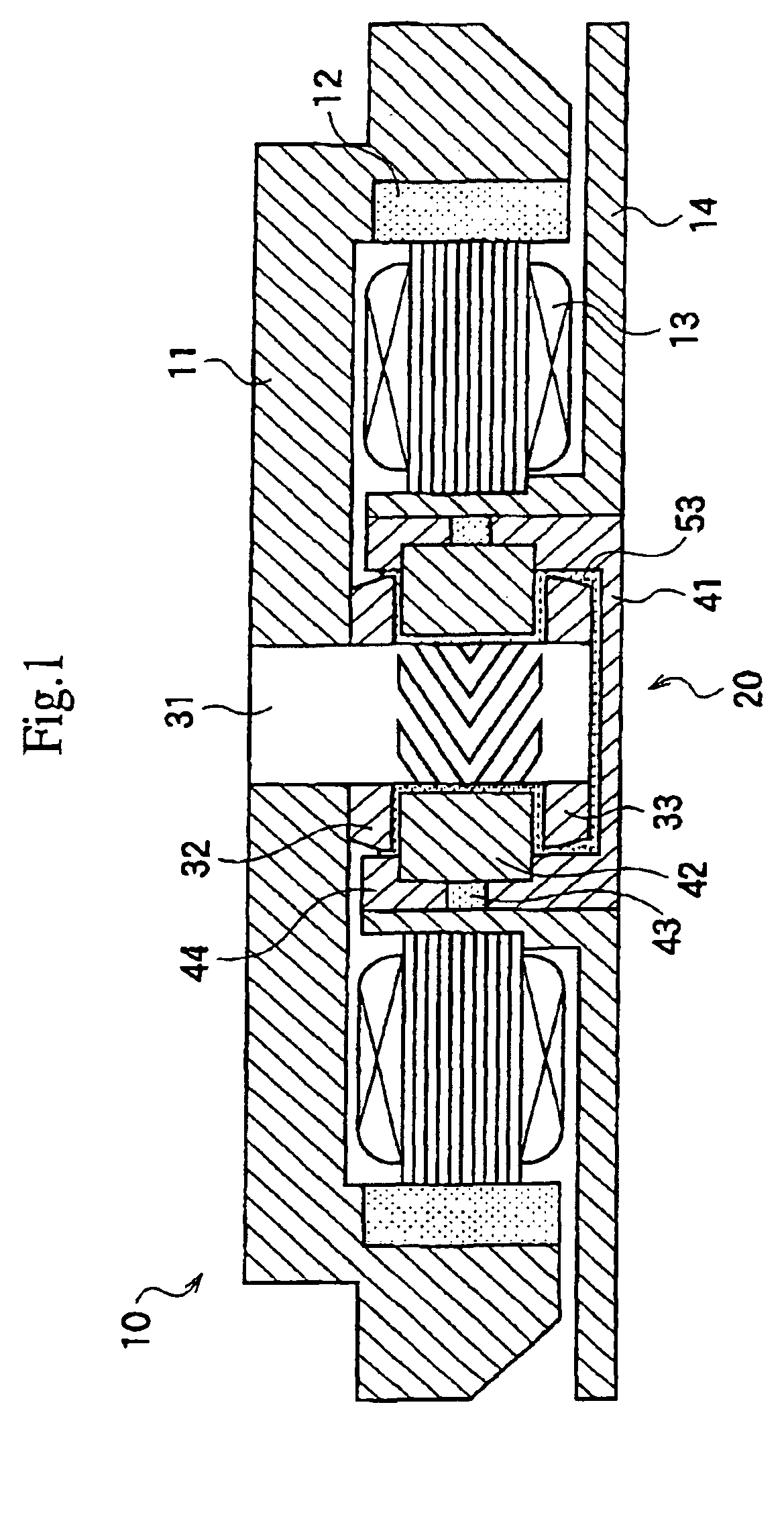
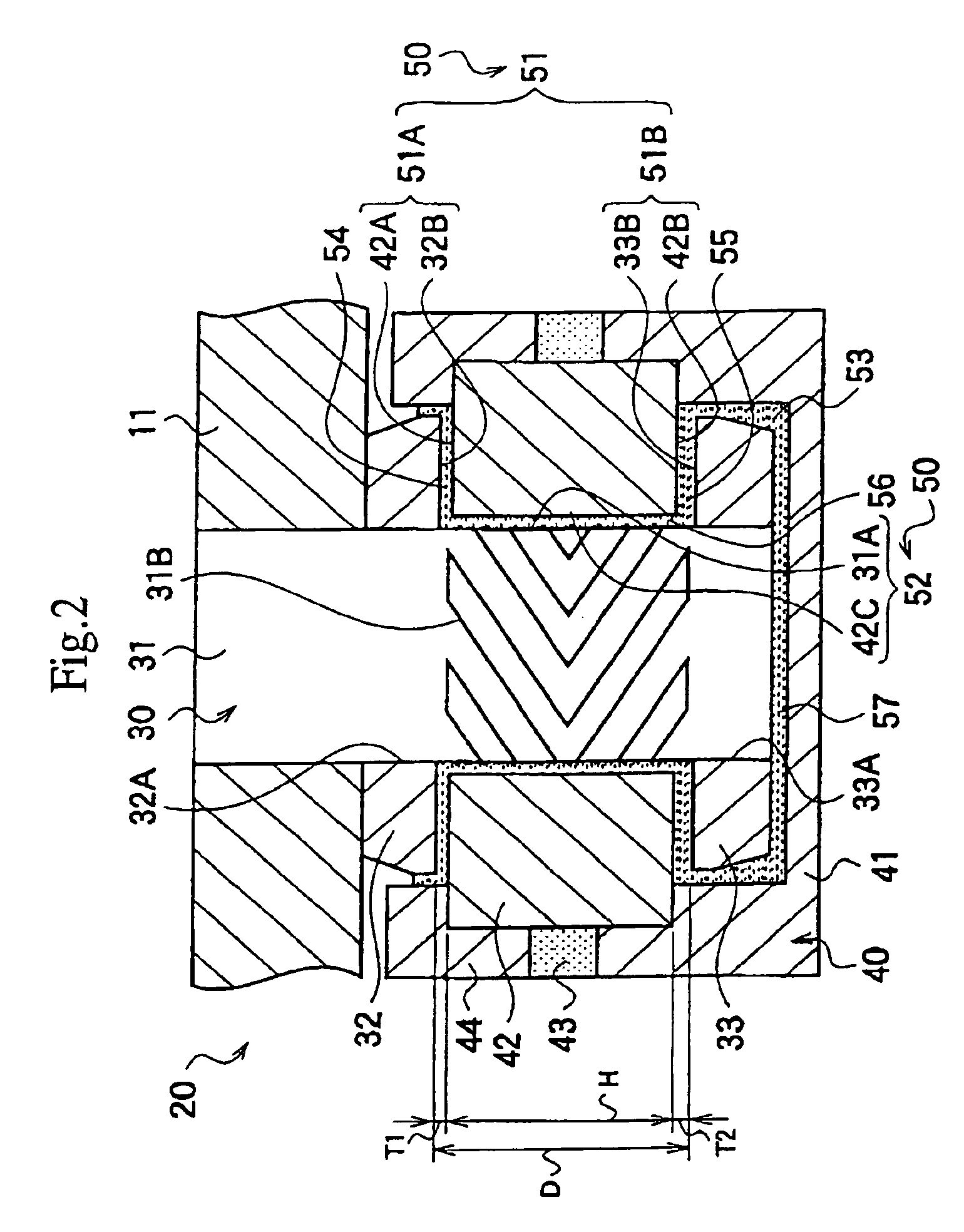
[0103][First Embodiment]

[0104]FIG. 1 is a cross sectional view showing an example when a dynamic pressure bearing device 20 of a first embodiment of the present invention is incorporated in an HDD rotation driver 10, and FIG. 2 shows an enlarged cross sectional view of the dynamic pressure bearing device 20. FIG. 3 shows an enlarged cross sectional view of an essential part of the dynamic pressure bearing device 20.

[0105]In FIG. 1, the dynamic pressure bearing device 20 is disposed at a center part of the HDD rotation driver 10. A hub 11 on which a not-shown memory disk is mounted is fixedly fitted to an upper part of a rotating shaft member 31 which is disposed at the rotation center of this dynamic pressure bearing device 20 so that the hub 11 rotates along with the rotating shaft member 31. A magnet member 12 for driving a motor is fixedly fitted to an inner peripheral surface of the hub 11, and a motor stator portion 13 fixed to a stator supporting member 14 is provided inside t...

second embodiment

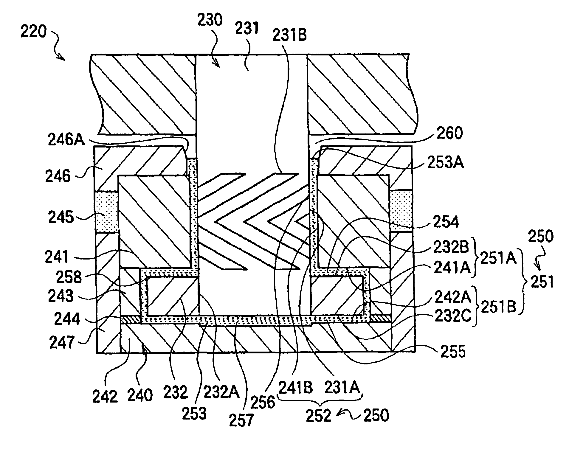
[0170][Second Embodiment]

[0171]FIG. 11 is a cross sectional view showing an example when a dynamic pressure bearing device 220 of a second embodiment of the present invention is incorporated into an HDD rotation driver 210, and FIG. 12 shows an enlarged cross sectional view of the dynamic pressure bearing device 220.

[0172]In FIG. 11, the dynamic pressure bearing device 220 is disposed at a center part of the HDD rotation driver 210. A hub 211 on which a not-shown memory disk is mounted is fixedly fitted to an upper part of a rotating shaft member 231 which is disposed at the rotation center of this dynamic pressure bearing device 220 so that the hub 211 rotates along with the rotating shaft member 231. A magnet member 212 for driving a motor is fixedly fitted to an inner peripheral surface of the hub 211, and a motor stator portion 213 fixed to a stator supporting member 214 is provided inside this magnet member 212 for driving a motor. The magnet member 212 for driving a motor is d...


PUM

PropertyMeasurementUnit
outer radiusaaaaaaaaaa
particle diameteraaaaaaaaaa
outer diameteraaaaaaaaaa

Abstract

It is an object of the present invention to provide a miniaturized, high-precision, easy, and low-cost dynamic pressure bearing device and a manufacturing method thereof. In manufacturing a dynamic pressure bearing device, a first and a second ring-shaped member are fixedly fitted to an outer peripheral surface of a rotating shaft member to constitute a rotating portion, an intermediate member is disposed between these members to constitute a fixed portion, a thrust bearing portion is formed in gaps between the first and second ring-shaped members and the intermediate member, and a journal bearing portion is formed in a gap between the rotating shaft member of the rotating portion and the intermediate member, the first and second ring-shaped members being fixed only with an adhesive applied on surfaces thereof which is to be fitted to the rotating shaft member.

Description

BACKGROUND OF THE INVENTION[0001]1. Field of the Invention[0002]The present invention relates to a dynamic pressure bearing device including a fixed portion and a rotating portion supported rotatably by this fixed portion via a dynamic pressure bearing portion, and to a manufacturing method and an assembly jig thereof, and is applicable, for example, not only to a disk-rotating-type memory such as a drive unit for a hard disk drive (HDD) and a digital versatile disk (DVD) but also to a polygon mirror and so on.[0003]2. Description of Related Art[0004]A dynamic pressure bearing device is generally so structured that a dynamic pressure is given to an operating oil which is filled in a gap between a rotating portion including a rotating shaft and a fixed portion by utilizing a rotational force of the rotating shaft, and this dynamic pressure brings the rotating portion into a levitated state relative to the fixed portion, thereby supporting the rotating shaft rotatably.[0005]In this dy...

Claims


Application Information

Patent Timeline
Patent Type & Authority Patents(United States)
IPC IPC(8): F16C33/04F16C33/10G11B19/20H02K5/16F16C17/10F16C33/14F16C43/02
CPCF16C17/026F16C33/107G11B19/2009H02K5/1675Y10T29/53104F16C2370/12Y10T29/497Y10T29/49696F16C17/107
Inventor SATOH, KIMIO
Owner RELIAL CORP
Why Eureka
Try Eureka