Hydrodynamic plain bearing and method of lubricating and cooling the bearing

a technology of hydrodynamic plain bearing and lubricating method, which is applied in the direction of bearings, engine lubrication, shafts, etc., can solve the problems of relative high loss factor and rising losses of such lubricated bearings, and achieves a very substantial reduction of losses and consumption of lubricant, and a high load capacity. , the effect of largely or completely eliminating vibration

Inactive Publication Date: 2005-11-22
GLEITLAGERTECHN WEISSBACHER
View PDF12 Cites 20 Cited by
  • Summary
  • Abstract
  • Description
  • Claims
  • Application Information

AI Technical Summary

Benefits of technology

[0013]It is the primary object of this invention to overcome the indicated disadvantages while providing a structurally relatively simple bearing with at least one fixed gliding plane, and to reduce the losses and consumption of lubricant very substantially while assuring a relatively high load capacity and largely or completely eliminating vibrations.

Problems solved by technology

The journal bearing disclosed in this patent is completely covered by the lubricant and has a relatively high loss factor, the losses of such lubricated bearings rising with proportionally with the surface covered by the lubricant.

Method used


Image

  • Hydrodynamic plain bearing and method of lubricating and cooling the bearing
  • Hydrodynamic plain bearing and method of lubricating and cooling the bearing
  • Hydrodynamic plain bearing and method of lubricating and cooling the bearing

Examples


Embodiment Construction

[0042]To avoid redundancy in the description, like parts operating in a like manner have been designated by the same reference numerals in all figures of the drawing.

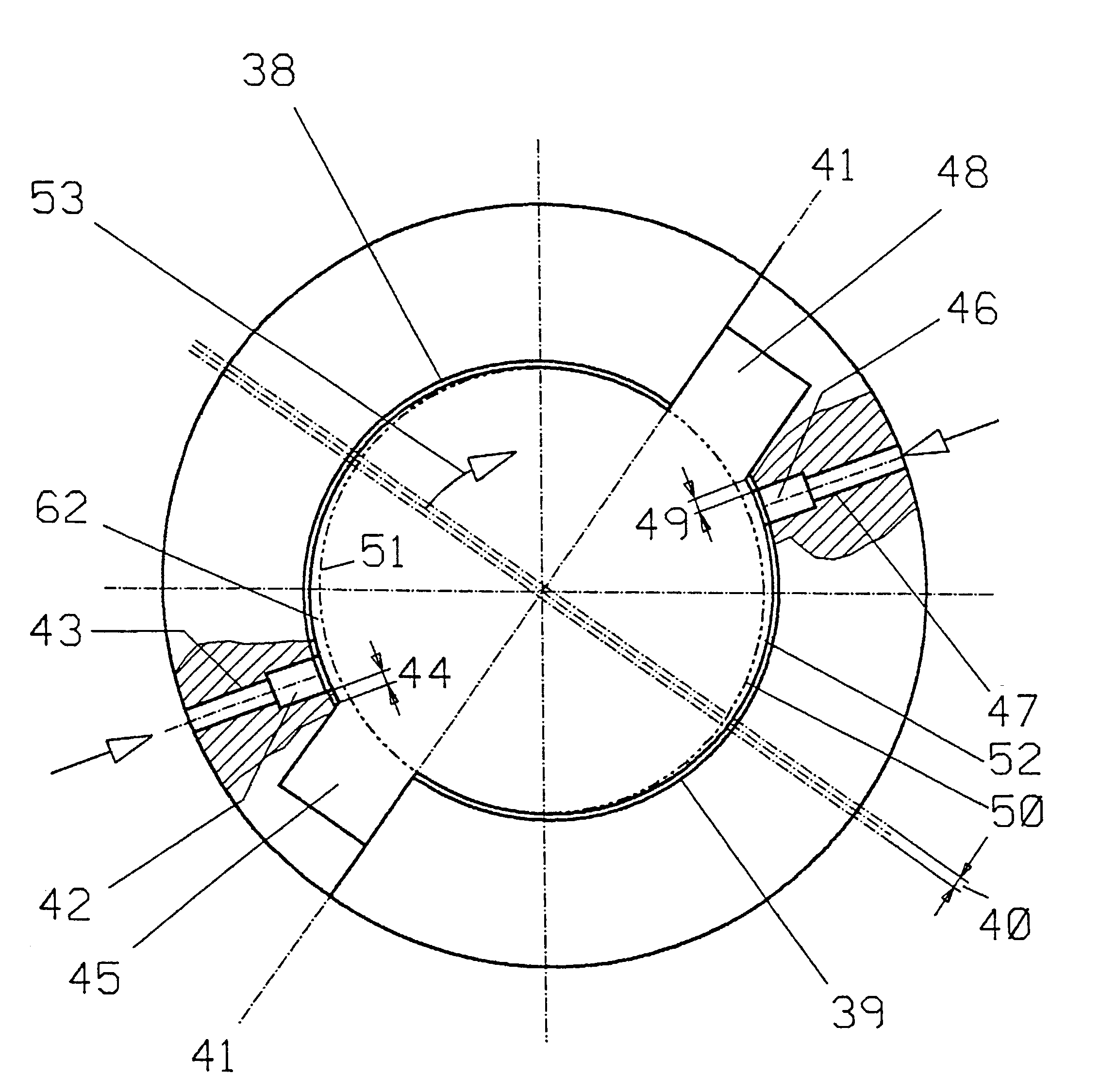
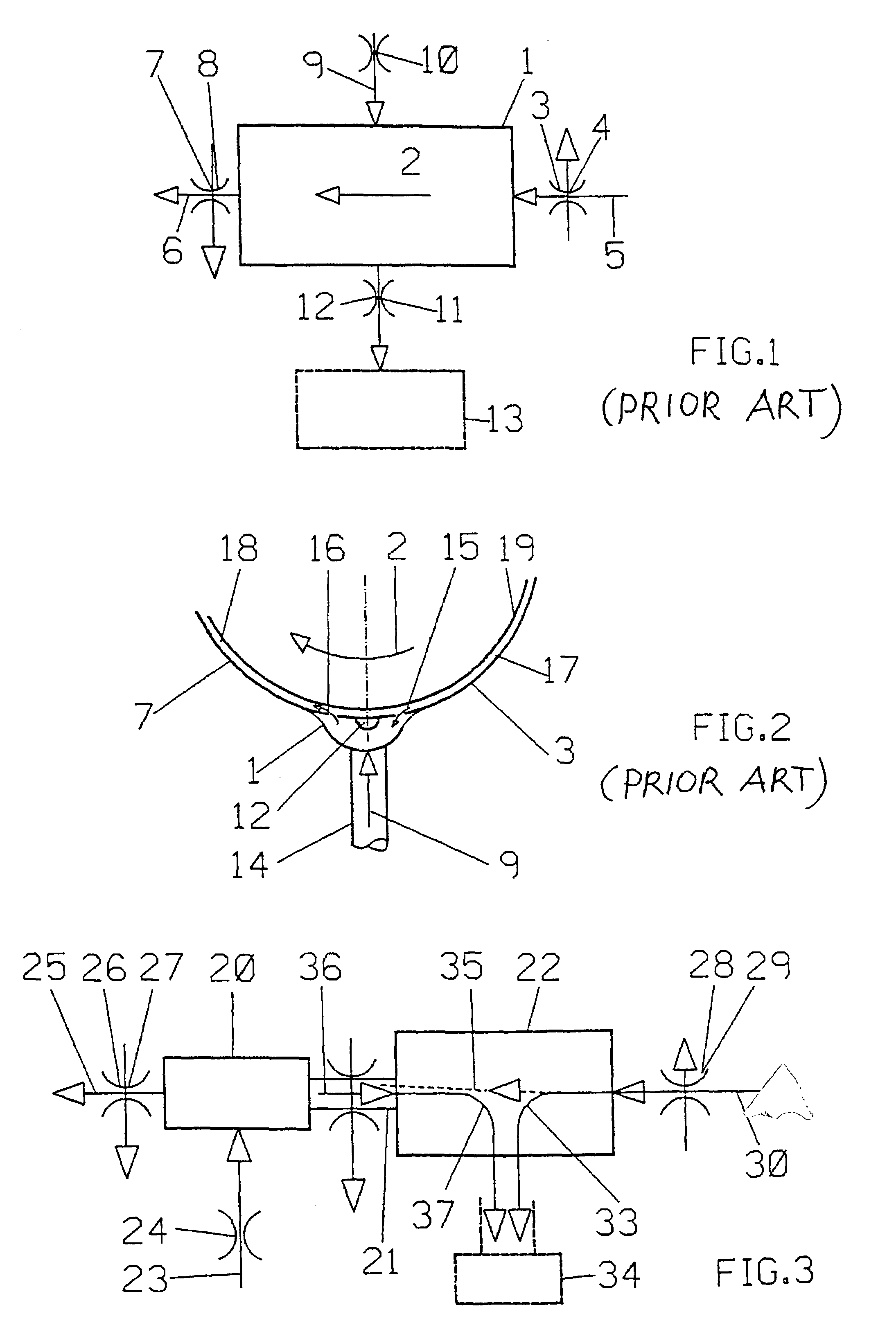
[0043]Referring first to FIGS. 1 and 2 schematically illustrating the prior art, shaft 19 rotates in a direction of rotation indicated by arrow 2, gliding past upstream gliding plane 3, as seen in the direction of rotation, and downstream gliding plane 7 of a plan bearing. The gliding planes and the circumference of shaft 19 define throttles 4 and 8 therebetween. Used, hot lubricant flows in the direction of arrow 5 through throttle 4 into lubricant pocket 1 to which fresh, cold lubricant is supplied under pressure in a direction indicated by arrow 9 through conduit 14 constituting a throttle 10. The used and the fresh lubricants are mixed in the lubricant pocket, and a portion of this mixture flows out of the lubricant pocket in the direction indicated by arrow 6 towards downstream gliding plane 7 which defines throttl...


PUM


Abstract

A method of lubricating and cooling a hydrodynamic plain bearing for a rotating element comprises the steps of supplying fresh, cold lubricant under pressure from a pressure chamber arranged upstream of a fixed gliding plane to a lubricating gap between the fixed gliding plane and the rotating element, the supply of fresh, cold lubricant being so controlled that an effective lubricating wedge is formed between the rotating element and the fixed gliding plane. The pressure chamber is connected to a decompression chamber predominantly filled with gas and arranged upstream of the pressure chamber by a mixing conduit, used, hot lubricant adhering to the rotating element is moved to the decompression chamber, and a portion of the used, hot lubricant is removed from the decompression chamber while the remaining portion of the used, hot lubricant flows from the decompression chamber into the mixing conduit and is mixed with fresh, cold lubricant flowing countercurrently in the mixing conduit whence the mixture is pressed into the decompression chamber.

Description

CROSS-REFERENCE TO RELATED APPLICATION[0001]This is a continuation-in-part of my U.S. patent application Ser. No. 09 / 888,239, filed Jun. 22, 2001 now abandoned.BACKGROUND OF THE INVENTION[0002]1. Field of the Invention[0003]The present invention relates to a method of lubricating and cooling a hydrodynamic plain bearing for a rotating element, which bearing has at least one fixed gliding plane, and a pressure chamber and a decompression chamber are arranged upstream of the gliding plane, wherein a fresh, cold lubricant is supplied under pressure from the pressure chamber to a lubricating gap between the rotating element and the fixed gliding plane at an entry end, the lubricant supply being so controlled that a sufficient lubrication wedge is created between the rotating element and the gliding plane, and used, hot lubricant is removed therefrom at a discharge end of the gliding plane and is conducted from the lubricating gap into the decompression chamber, any hot lubricant adherin...

Claims


Application Information

Patent Timeline
Patent Type & Authority Patents(United States)
IPC IPC(8): F16C33/04F16C33/10F16C37/00F16C17/02F16C17/04
CPCF16C17/02F16C17/04F16C33/1075F16C37/002F16N2210/14F16C17/028F16C17/047
Inventor WEISSBACHER, GEORG
Owner GLEITLAGERTECHN WEISSBACHER
Why Eureka
Try Eureka