Exhaust gas purifying catalyst

a purifying catalyst and exhaust gas technology, applied in the direction of physical/chemical process catalysts, other chemical processes, separation processes, etc., can solve the problems of insufficient action of the purifying catalyst in the atmosphere where oxygen is short, and the inability to purify nox in good balance,

Inactive Publication Date: 2005-11-22
NISSAN MOTOR CO LTD
View PDF37 Cites 38 Cited by
  • Summary
  • Abstract
  • Description
  • Claims
  • Application Information

AI Technical Summary

Benefits of technology

[0015]An object of the present invention is to provide an exhaust gas purifying catalyst that purifies HC discharged in the low temperature range at the time of starting up the engine more efficiently.

Problems solved by technology

However, since the starting temperature of HC desorption is lower than the starting temperature of three-way catalyst activation, early-desorbed HC is discharged without being purified by the three-way catalyst in the HC-trap catalyst.
Moreover, since an oxidation reaction occurs when the adsorbed HC is desorbed and purified, an atmosphere around the purifying catalyst layer of the HC-trap catalyst falls in a state of oxygen shortage.
Since the three-way catalyst exhibits the best action of the purifying catalyst in the range of the stoichiometric air / fuel ratio, it cannot exert the action of the purifying catalyst sufficiently in the atmosphere where oxygen is short.
Therefore, HC, CO and NOx cannot be purified in good balance, and it becomes difficult to enhance the purification efficiency for the cold HC sufficiently.
However, these methods are costly because of complex system configurations, and purification efficiency for the cold HC cannot be sufficiently enhanced.

Method used


Image

  • Exhaust gas purifying catalyst
  • Exhaust gas purifying catalyst
  • Exhaust gas purifying catalyst

Examples


first embodiment

(First Embodiment)

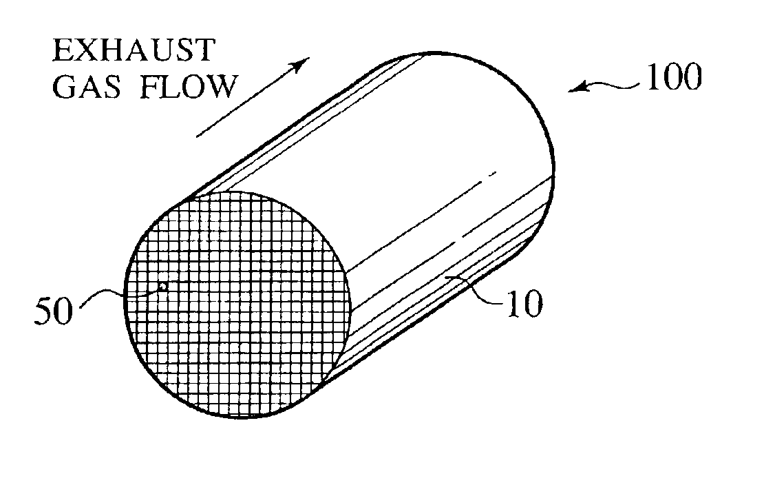
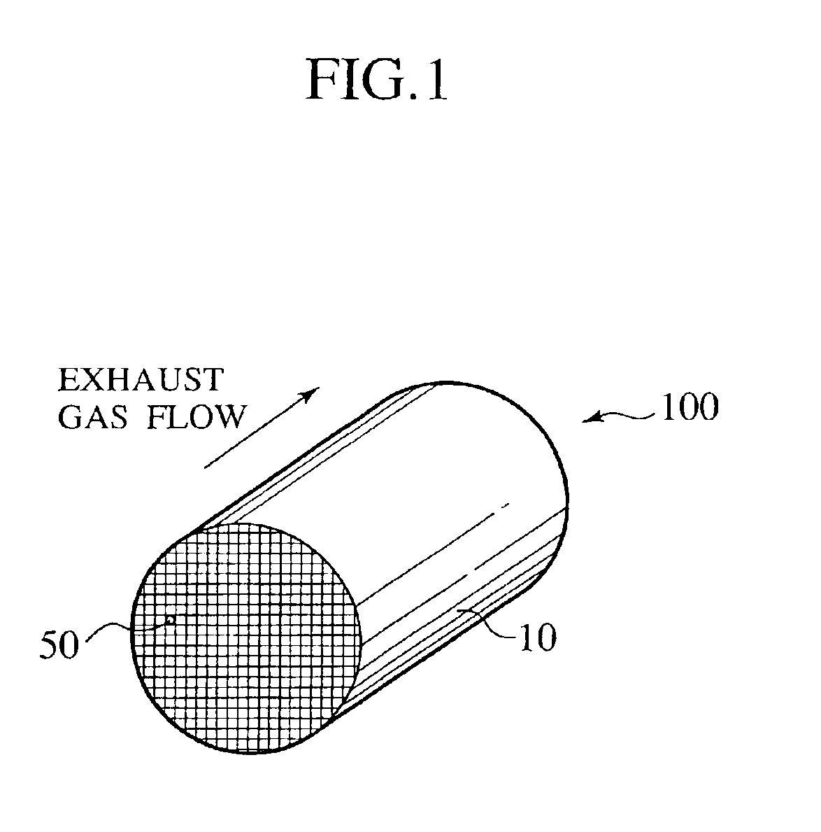
[0029]As shown in FIG. 1, an exhaust gas purifying catalyst according to a first embodiment of the present invention is an HC-trap catalyst 100 that has an HC adsorbent layer and a catalyst layer in a honeycomb carrier 10 having a plurality of cells 50 serving as exhaust gas passages.

[0030]The HC-trap catalyst 100 according to the first embodiment is characterized by including a purifying catalyst layer composed differently on an upstream side and a downstream side of an exhaust gas flow.

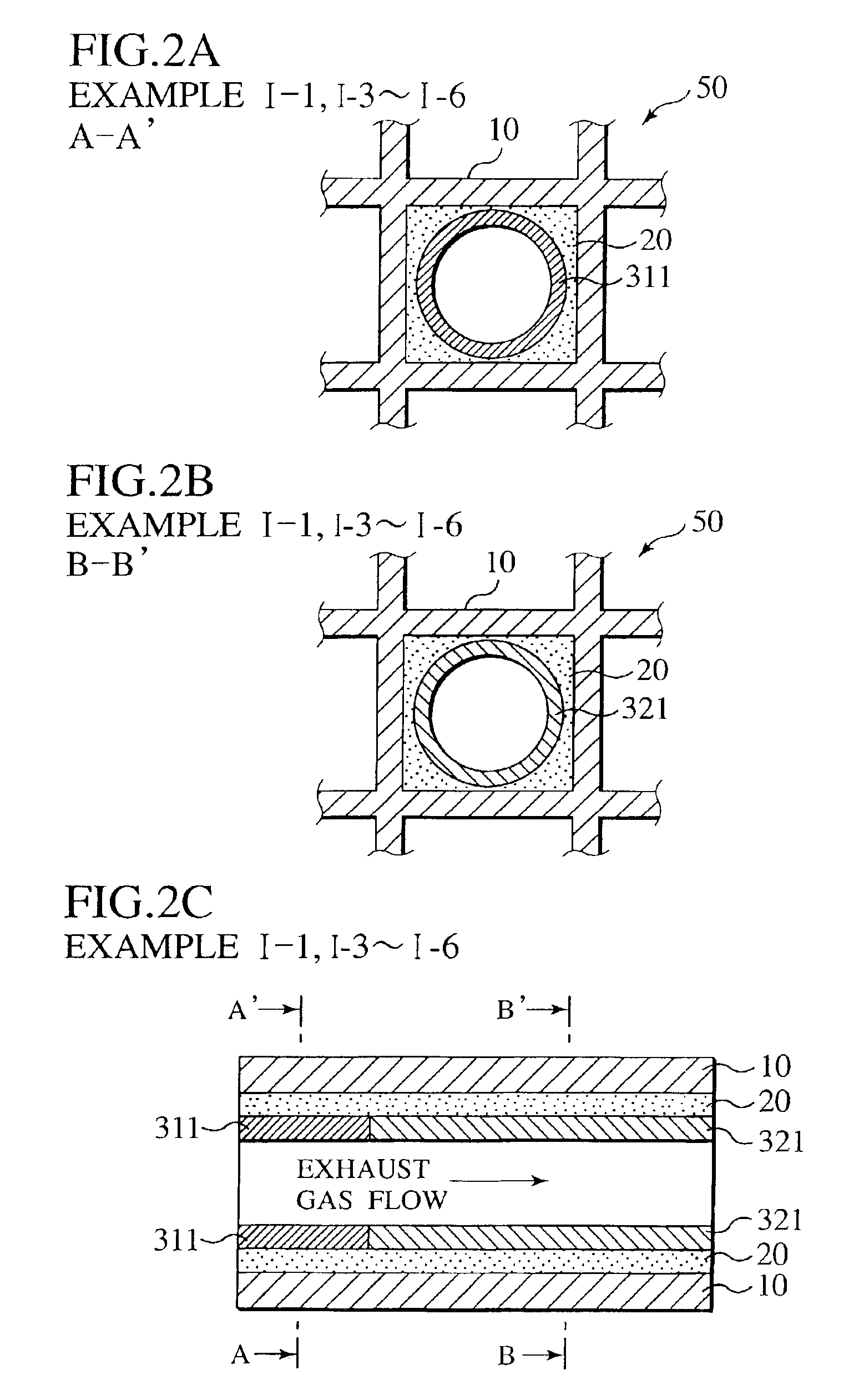
[0031]FIGS. 2A to 2C show the cell structure of the HC-trap catalyst 100 according to the first embodiment. As shown in FIGS. 2A to 2C, an HC adsorbent layer 20 mainly containing zeolite is formed on the carrier 10 of each cell, and the purifying catalyst layer is formed on the HC adsorbent layer 20. The purifying catalyst layer is divided into an upper catalyst layer 311 disposed on the upstream side of the exhaust gas flow and a lower catalyst layer 321 disposed on the downstream...

examples i

[0052]The table of FIG. 6A shows specifications of catalysts in examples I-1 to I-9, and the table of FIG. 6B shows specifications of catalysts in comparative examples I-1 to I-5.

example i-1

[0053]FIGS. 2A to 2C show the structure of the HC-trap catalyst of the example I-1. In the HC-trap catalyst of the example I-1, the upper catalyst layer 311 contains Pd-supported Ce-[A]-Ob. Concretely, as Ce-[A]-Ob, La0.01Ce0.69Zr0.3Ob was used. The lower catalyst layer 321 contains Pd-supported Ce—Al2O3.

[0054]The respective catalyst layers were prepared by the following methods.

20>

[0055]800 g of β-zeolite powder (Si / 2Al=35), 1333.3 g of silica sol (solid part 15%) and 1000 g of pure water were poured into a ball mill pot made of alumina, then were milled for 60 minutes, and thus a slurry solution was obtained. This slurry solution was coated on a monolithic carrier of 300 cells / 6 mills (46.5 cells / cm2, wall thickness 0.0152 cm) and of a catalyst capacity 1.0 L, dried for 30 minutes in an air flow of 50° C. after removing extra slurry in the cells by an air flow, then baked at 400° C. for an hour after drying for 15 minutes in an air flow of 150° C. The weight of the coating layer a...


PUM

PropertyMeasurementUnit
particle diameteraaaaaaaaaa
temperatureaaaaaaaaaa
thicknessaaaaaaaaaa

Abstract

An exhaust gas purifying catalyst including a carrier having a plurality of cells as exhaust gas passages, an HC adsorbent layer formed on the carrier of each of the cells, and an upper catalyst layer disposed on an upstream side of each of the exhaust gas passages on the HC adsorbent layer and a lower catalyst layer disposed on a downstream side of each of the exhaust gas passages on the HC adsorbent layer. The upper catalyst layer includes more O2-storage material than the lower catalyst layer, and the lower catalyst layer includes a catalyst having a wider activation range than the upper catalyst layer.

Description

BACKGROUND OF THE INVENTION[0001]1. Field of the Invention[0002]The present invention relates to an exhaust gas purifying catalyst that purifies carbon monoxide (CO), hydrocarbons (HC) and nitrogen oxides (NOx) in exhaust gas discharged from an internal combustion engine of a gasoline or diesel automobile, a boiler or the like. More particularly, the present invention relates to an exhaust gas purifying catalyst that purifies a large amount of HC discharged in a low temperature range at time of starting up an engine, in which a three-way catalyst is not activated.[0003]2. Description of the Related Art[0004]Heretofore, in order to purify exhaust gas from an internal combustion engine of an automobile or the like, a three-way catalyst that simultaneously performs oxidation for carbon monoxide (CO) and hydrocarbons (HC) and reduction for nitrogen oxides (NOx) has widely been used. However, since the temperature of the exhaust gas is low and the three-way catalyst disposed on an exhaus...

Claims


Application Information

Patent Timeline
Patent Type & Authority Patents(United States)
IPC IPC(8): B01J23/54B01J23/63B01D53/94B01J37/02B01J37/00F01N3/08F01N3/28B01J35/00F01N7/02F01N7/00F01N3/24B01J23/58B01J35/04F01N13/02
CPCB01D53/945B01D53/9454B01J23/63B01J37/0244B01J37/0246F01N3/0814F01N3/0835F01N3/2828F01N13/009F01N13/0097B01D53/9477B01D2255/1021B01D2255/1023B01D2255/1025B01D2255/206B01D2255/20715B01D2255/502B01D2255/902B01D2255/908B01D2255/912B01D2255/92B01J35/0006F01N2370/04F01N2510/06F01N2510/0682F01N2510/0684F01N2570/16Y02T10/22Y02T10/12
Inventor TAKAYA, MASAHIROYAMAMOTO, SHINJIHIRAMOTO, YOSHIAKI
Owner NISSAN MOTOR CO LTD
Why Eureka
Try Eureka