Radar apparatus, and program therefor

a technology of radar and target, applied in the field of radar apparatus, can solve the problems of difficult detection of target peak, complication and size expansion of the apparatus, and achieve the effect of accurate detection

Inactive Publication Date: 2005-11-29
DENSO CORP
View PDF13 Cites 22 Cited by
  • Summary
  • Abstract
  • Description
  • Claims
  • Application Information

AI Technical Summary

Benefits of technology

[0013]The present invention has been developed in order to solve these problems, and it is therefore an object of the invention to provide a radar apparatus capable of stably and continuously detecting a target even if a reflected wave (peak frequency component) from a target already detected falls into obscurity due to the presence of low-frequency noises or reflected waves from other targets.
[0018]That is, according to the present invention, even in a case in which a peak frequency component corresponding to only one of a pair of estimated values is detectable, if the non-detectable peak frequency component meets an extrapolation condition and it previously turns out that the peak frequency component will not be detected, it is processed as having been detected. This enables stable target detection.
[0020]Moreover, preferably, in a case in which a plurality of channels each comprising a transmitting antenna and a receiving antenna exist and a beat signal is obtainable for each channel, in obtaining an azimuth (direction) angle of a target specified by a peak pair extrapolated by the extrapolation means, the actual azimuth angle is obtained on the basis of one peak frequency component detected in each channel. In this case, even for the target specified by the extrapolated peak pair, the information on the azimuth angle is accurately obtainable.
[0021]Furthermore, the radar apparatus according to the present invention can continuously detect, for example, an approaching target up to the collision moment without losing halfway and, hence, it can be mounted on a vehicle to be suitable for use in the inter-vehicle distance control, pre-crush control, and the like.

Problems solved by technology

For this reason, if a peak develops in a region NA in which the low-frequency noise occurs (which will be referred to hereinafter as a “low-frequency noise region”), difficulty is experienced in extract this peak (see FIG. 9B), which makes it difficult to detect a target which has produced the peak.
However, in this apparatus, in addition to the employment of the configuration of the FMCW radar, there is a need to use an oscillator, mixer, filter and other devices for production and processing of a signal in an intermediate frequency band, which leads to the complication and size-expansion of the apparatus and, hence, an increase in manufacturing cost.
In addition, in the case of tracking a preceding vehicle through the use of the FMCW radar, if the tracked preceding vehicle gets between roadside things or travels side by side with another preceding vehicle, on the power spectrum, the peak stemming from the tracked preceding vehicle falls into obscurity due to the peaks from the roadside things or the other preceding vehicles, as in the case of the low-frequency noise, difficulty is encountered in detecting this peak from the tracked preceding vehicle.
Add to it that, because the peaks from the roadside things or the other preceding vehicles do not always develop in a constant frequency band unlike the flow-frequency noise, the apparatus disclosed in the aforesaid document cannot cope with such a situation.

Method used


Image

  • Radar apparatus, and program therefor
  • Radar apparatus, and program therefor
  • Radar apparatus, and program therefor

Examples


Embodiment Construction

[0034]An embodiment of the present invention will be given hereinbelow with reference to the drawings.

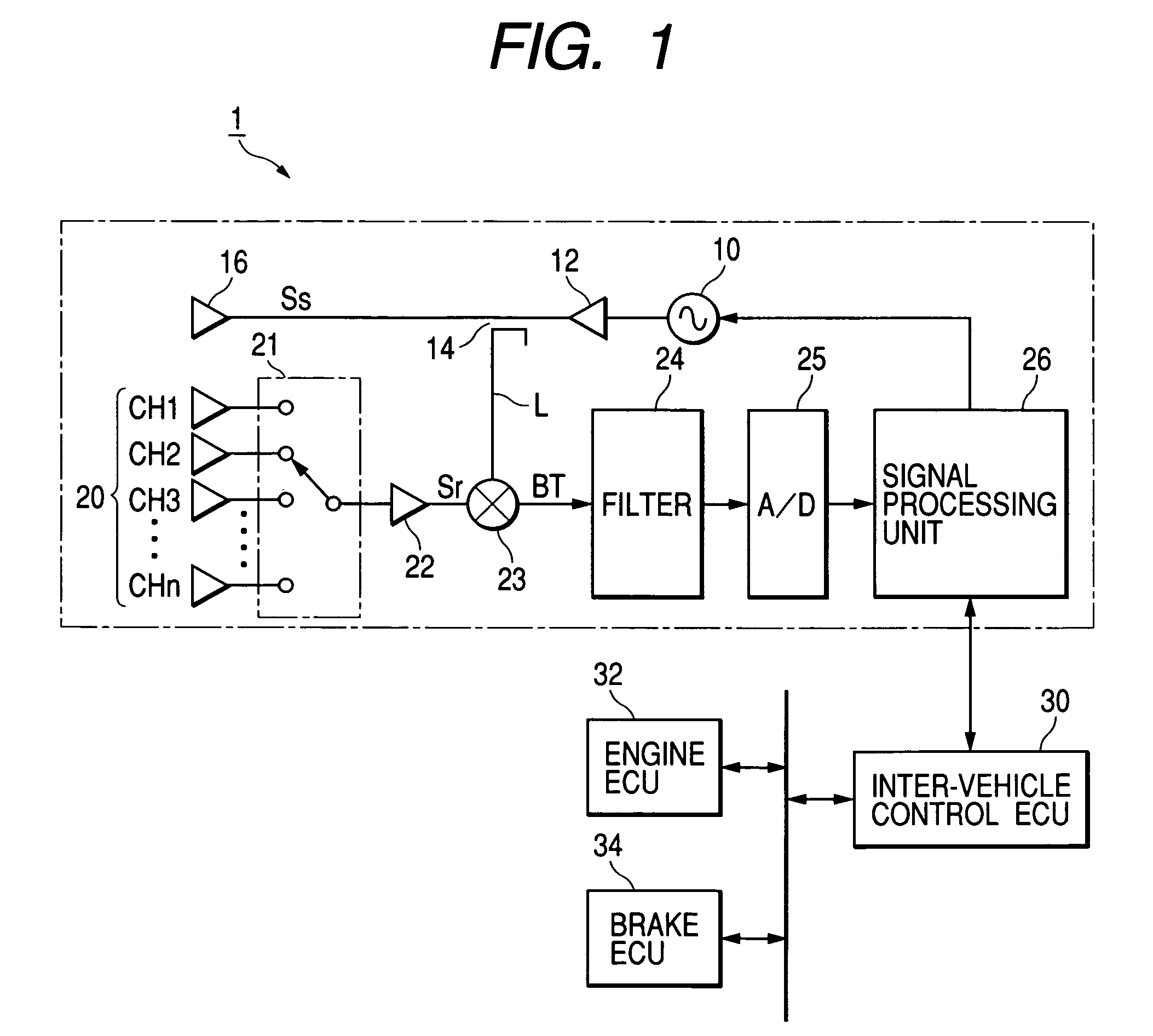
[0035]FIG. 1 is a block diagram showing the outline of a configuration of a cruise control system based upon the present invention.

[0036]In FIG. 1, the cruise control system is made up of an inter-vehicle control electronic control unit (which will be referred to hereinafter as an “inter-vehicle control ECU”) 30, and engine electronic control unit (which will be referred to hereinafter as an “engine ECU”) 32 and a brake electronic control unit (which will be referred to hereinafter as a “brake ECU”) 34, which are connected through LAN communication buses to each other. Moreover, each of the ECUs 30, 32 and 34 is based on a well-known microcomputer and is equipped with at least a bus controller for making communications through the LAN communication buses. Incidentally, in this embodiment, the data communications among the ECUs are made through the use of a CAN (“Controller Area Netw...


PUM


Abstract

Provided is a radar apparatus capable of continuously and stably making a detection of a target even if a reflected wave from a target already detected falls into obscurity due to the presence of low-frequency noises or reflected waves from other targets. An estimated value of information on a target to be obtained when the target is detected in the present cycle are acquired from the target detected in a previous cycle. When a peak compatible with the estimated value is detected in only one of a frequency-rising section and a frequency falling section of a radar wave, if the frequency of the non-detected peak pertains a low-frequency noise domain or if a side-by-side travel flag is set with respect to the target detected in the previous cycle, the non-detected peak is considered as buried by low-frequency noises or peaks of other targets, and a peak pair corresponding to the detected target is extrapolated.

Description

BACKGROUND OF THE INVENTION[0001]1) Field of the Invention[0002]The present invention relates to a radar apparatus designed to process a beat signal forming a mixture of transmitted and received signals on a radar wave for detecting a target which has reflected the radar wave.[0003]2) Description of the Related Art[0004]So far, an FMCW type radar using a millimetric-wave band (which will be referred to hereinafter as an “FMCW radar”) has been known as one of vehicle-mounted radars applicable to, for example, an inter-vehicle distance control apparatus made to detect a vehicle (preceding vehicle) existing in a forward direction for maintaining the inter-vehicle distance properly with respect thereto or an inter-vehicle distance alarm apparatus made to make a notification to the driver when the inter-vehicle distance becomes shorter than a predetermined distance.[0005]This FMCW radar uses a radar wave modulated such that the frequency increases and decreases (rises and falls) linearly...

Claims


Application Information

Patent Timeline
Patent Type & Authority Patents(United States)
IPC IPC(8): B60K31/00G01S13/931G01S13/34G01S13/58G08G1/16
CPCG01S13/345G01S13/931G01S7/354G01S13/584Y02T10/84G01S2013/9325G01S2013/9346G01S2013/935G01S2013/9353G01S2013/9319G01S2013/93185G01S2013/932
Inventor KUMON, HIROAKITAMATSU, YUKIMASA
Owner DENSO CORP
Why Eureka
Try Eureka