
Electronic imaging apparatus operable in two modes with a different optical black correction procedure being effected in each mode

a technology of optical black correction and electronic imaging apparatus, which is applied in the direction of color signal processing circuit, television system, radio control device, etc., can solve the problems of inability to apply a pickup apparatus for performing special drives, image quality deterioration, and new fixed-pattern noise, etc., to achieve adequate suppression of the effect of random noise and high image quality

Inactive Publication Date: 2005-11-29
OLYMPUS CORP
View PDF10 Cites 57 Cited by
  • Summary
  • Abstract
  • Description
  • Claims
  • Application Information

AI Technical Summary

Benefits of technology

[0009]To solve the above described problems in the image pickup apparatus having the conventional smear correction means, it is an object of the present invention to provide an image pickup apparatus in which, even if a plurality of image pickup device drive modes are provided, a favorable smear correction can be performed in respect of each drive mode with reducing to a minimum such problems as occurrence of newly added noise due to the correction processing.
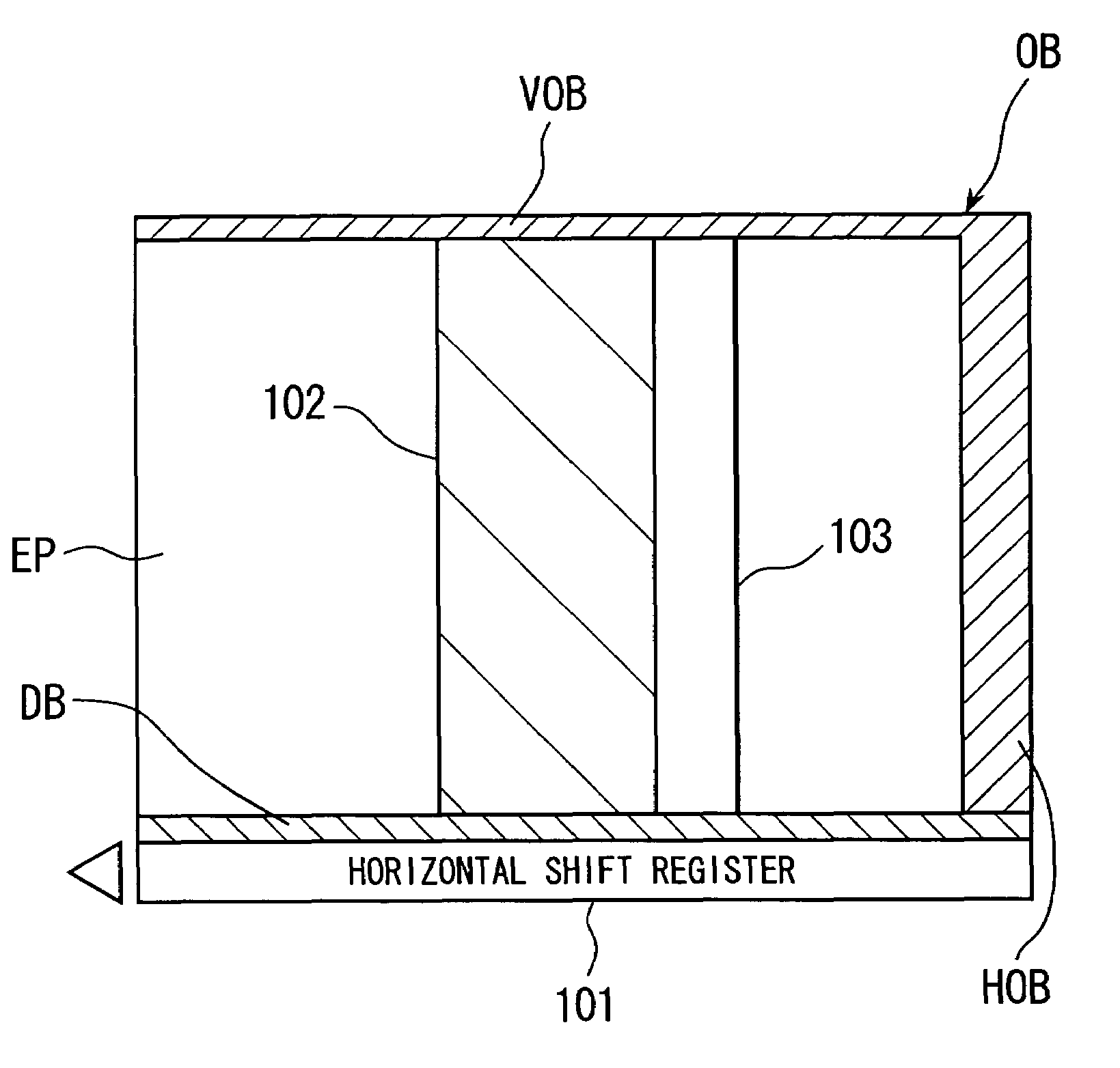
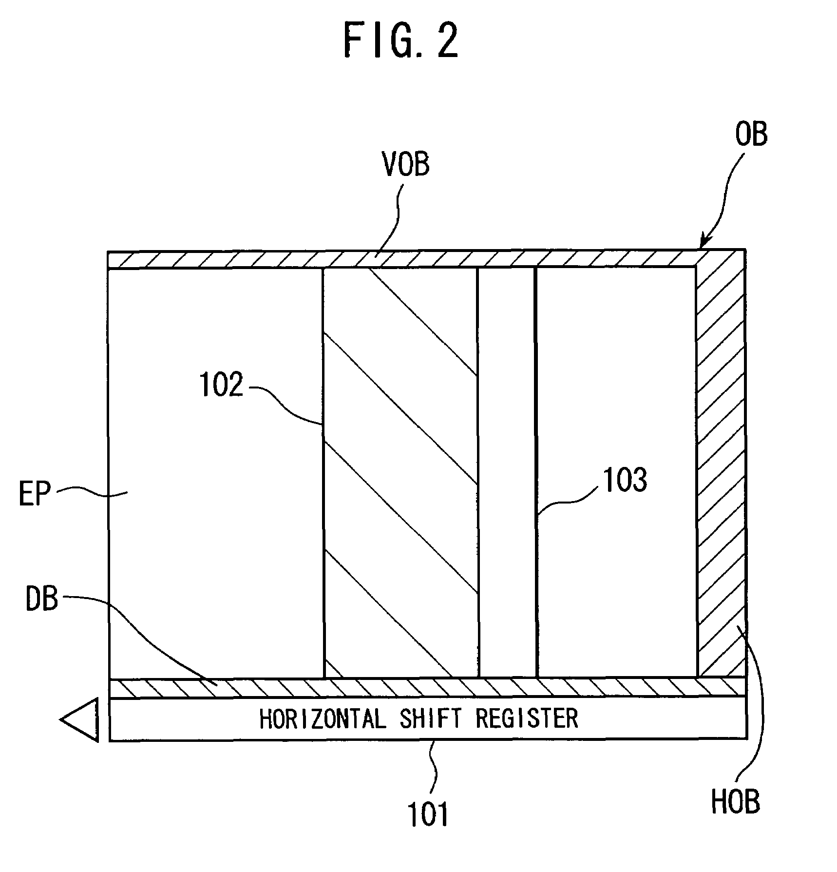
[0011]By thus performing different types of correction reference signal generation processing corresponding to the plurality of drive modes, the image pickup apparatus can be achieved as capable of favorable smear correction for each drive mode with reducing to a minimum such problems as occurrence of newly added noise due to the correction processing. The above object is thereby accomplished.
[0012]It is another object of the invention to provide an image pickup apparatus having as drive modes a normal mode and n-addition mode, capable of favorable smear correction with reducing to a minimum such problems as occurrence of newly added noise due to pixel defect.
[0014]By using such construction, it becomes possible to perform favorable smear correction for normal mode and for n-addition mode with reducing to a minimum such problems as occurrence of newly added noise due to pixel defect. In other words, a true smear correction can be performed even at the time of an addition mode for example by performing a level processing of correction reference signal corresponding to the added number. The above object is thereby accomplished.
[0015]It is a further object of the invention to provide an image pickup apparatus in which a smear correction of high image quality can be performed without causing an occurrence of newly added noise due to pixel defect and at the same time with adequately suppressing the effect of randomized noise.
[0017]By using such construction, since, even in n-addition mode, readout by normal drive mode is exceptionally performed when reading out the vertical 0B pixel signals, newly added noise due to pixel defect does not occur. Further it becomes possible to perform smear correction of high image quality with adequately suppressing the effect of randomized noise. The above object is thereby accomplished.

Problems solved by technology

In conventional solid-state image pickup apparatus using CCD image pickup device, there is a problem of image quality deterioration due to smears which occur as a phenomenon peculiar to CCD image pickup device when an intense light has been incident thereupon.
In particular, such phenomenon occurs as charge not captured at its true charge accumulating region is caused to leak into the vertical transfer line across the potential barrier.
Since the smear correction method described above as a prior-art technique premises a normal drive, it cannot be applied to an image pickup apparatus for performing special drive such as the above described n-addition drive.
Hence there is another problem that additional fixed-pattern noise is newly caused to the contrary due to the correction.

Method used


Image

  • Electronic imaging apparatus operable in two modes with a different optical black correction procedure being effected in each mode
  • Electronic imaging apparatus operable in two modes with a different optical black correction procedure being effected in each mode
  • Electronic imaging apparatus operable in two modes with a different optical black correction procedure being effected in each mode

Examples


Embodiment Construction

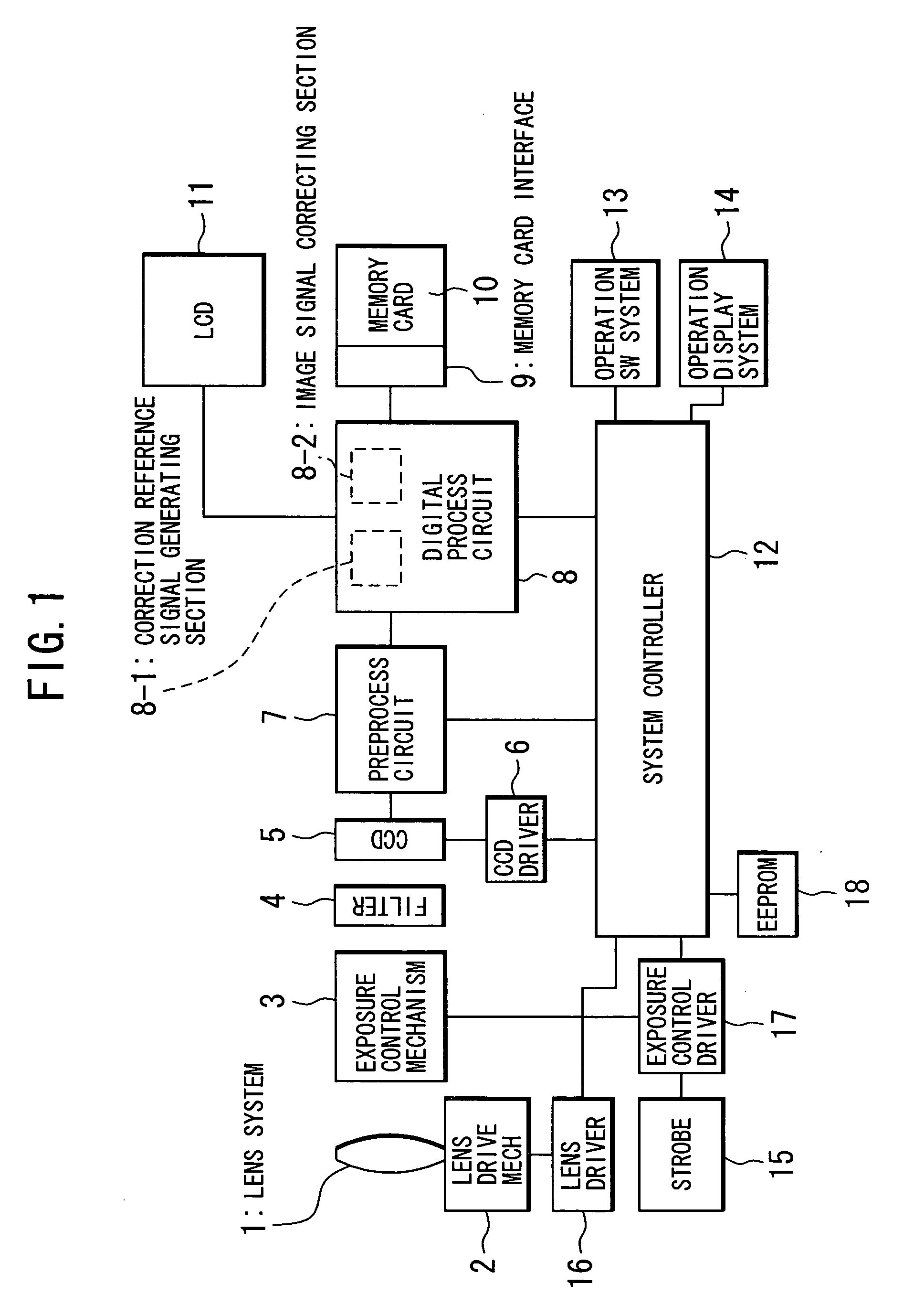
[0025]An embodiments of the present invention will now be described. FIG. 1 is a block diagram showing a digital camera as a first embodiment of the image pickup apparatus according to the invention. Included are: 1, lens system; 2, lens drive mechanism; 3, exposure control mechanism; 4, filter system; 5, CCD image pickup device; 6, CCD driver; 7, preprocess circuit including an analog-to-digital converter; 8, digital process circuit including a memory as hardware, for performing all the digital processing. Also shown are: 9, memory card interface; 10, memory card; 11, LCD image display system; 12, system controller including a microcomputer as its main component; 13, operation switch system; 14, operation display system including an indicating LCD; 15 strobe; 16, lens driver; 17, exposure control driver; 18, EEPROM.

[0026]In thus constructed digital camera, all the control is generally performed by the system controller 12 which, in particular, controls a shutter device in the expos...


PUM


Abstract

An image pickup apparatus including: CCD image pickup device; a correction reference signal generating section for generating a correction reference signal for correcting effective image signals of the image pickup device from output signals of a vertical optical black pixel portion of the image pickup device; an image signal correcting section for subtracting the correction reference signal from an effective image signal; and CCD driver having a plurality of drive modes for driving the image pickup device to read pixel charges as output signals; wherein, when generating the reference signal, said correction reference signal generating section performs different types of reference signal generation processing corresponding to the plurality of drive modes of the CCD driver.

Description

[0001]This application claims benefit of Japanese Application No. Hei 11-199750 filed in Japan on Jul. 14, 1999, the contents of which are incorporated this reference.BACKGROUND OF THE INVENTION[0002]The present invention relates to image pickup apparatus, and more particularly relates to an image pickup apparatus having a function for correcting false signals.[0003]In conventional solid-state image pickup apparatus using CCD image pickup device, there is a problem of image quality deterioration due to smears which occur as a phenomenon peculiar to CCD image pickup device when an intense light has been incident thereupon. In particular, such phenomenon occurs as charge not captured at its true charge accumulating region is caused to leak into the vertical transfer line across the potential barrier. If caused by an ordinary and steady light, such phenomenon occurs over a vertical transfer period. In the case of a spot light, it results in a vertical stripe extended up and down theref...

Claims


Application Information

Patent Timeline
IPC IPC(8): H01L27/148H04N5/347H04N5/359H04N5/361H04N5/367H04N5/372H04N9/64
CPCH04N5/343H04N5/3595H04N25/42H04N25/625
Inventor KIDONO, MASAMIYOSHIDA, HIDEAKI
Owner OLYMPUS CORP
Learn More