High-voltage low-distortion input protection current limiter

Inactive Publication Date: 2005-11-29
LINEARX SYST
View PDF35 Cites 33 Cited by
  • Summary
  • Abstract
  • Description
  • Claims
  • Application Information

AI Technical Summary

Benefits of technology

[0011]The present invention provides a current limiter circuit for limiting overload current and thereby preventing destruction of the input components of an input circuit, including the current limiter circuit itself The current limiter of the present invention is characterized by three regions of operation and provides a low-noise, highly-linear, low-value input impedance

Problems solved by technology

Such an arrangement, however, creates a condition in which exces

Method used


Image

  • High-voltage low-distortion input protection current limiter
  • High-voltage low-distortion input protection current limiter
  • High-voltage low-distortion input protection current limiter

Examples


Embodiment Construction

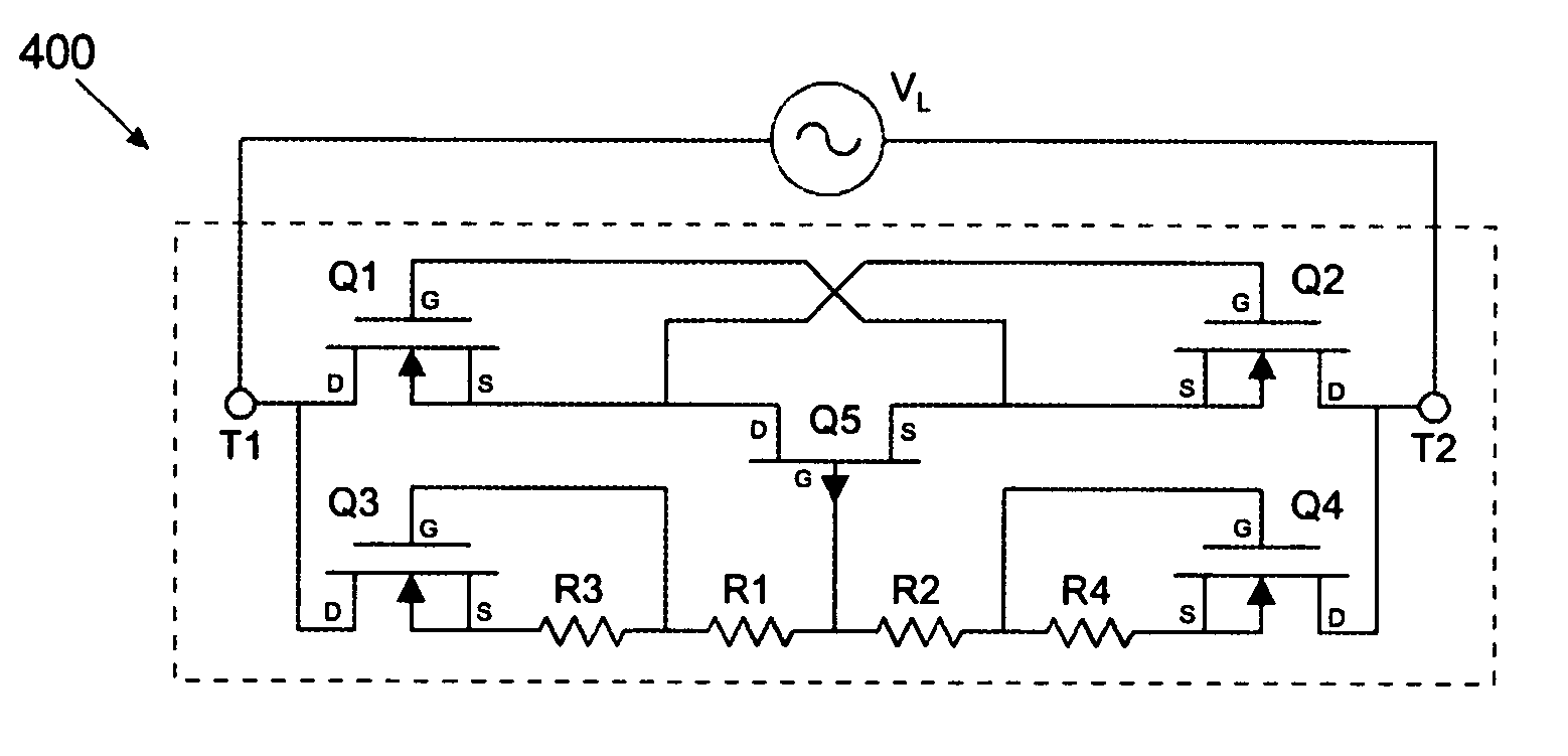
[0027]The present invention provides a current limiting circuit that protects input circuits from excessive current. One exemplary embodiment of a current limiting circuit of the present invention provides a bipolar floating limiter having four depletion-mode N-channel MOSFET transistors. The bipolar floating limiter is characterized by three regions of operation and provides a linear low-impedance input for normal-level small signals and a constant current source for overload signals. The four depletion mode N-channel MOSFET transistors provide high voltage overload capability. A single P-Channel JFET provides foldback current limiting during overload conditions, thereby providing low power dissipation. Four resistors are used for configuring the limiter characteristics. Under normal small-signal operation, the current limiter circuit of the present invention is inherently linear because only resistors and FETs are used.

[0028]FIG. 3 shows a schematic diagram of an exemplary embodim...


PUM


Abstract

A floating symmetrical current limiter device blocks large bipolar input signals to the input circuit of an instrumentation device by transitioning between a low-impedance mode and a high-impedance mode. The current limiter device includes a signal path and a control path that are each coupled between an input terminal and an output terminal. The signal path has a low impedance that passes small differential signals across the limiter from the input terminal to the output terminal. The control path is responsive to large bipolar signals that appear across the limiter terminals by transitioning between a voltage divider and a constant-current source-based bias that controls the impedance of the signal path to become a large impedance, thereby blocking the large bipolar input signal from the output terminal.

Description

BACKGROUND OF THE INVENTION[0001]1. Field of the Invention[0002]The present invention relates to a current limiter circuit for protecting input circuits. More particularly, the present invention relates to a current limiter circuit for protecting input circuits from excessive over-voltage conditions and excessive input currents, while providing low distortion for small-signal input voltages.[0003]2. Description of the Related Art[0004]Input circuits appear in a wide variety of applications, including instrumentation devices such as Digital Multimeters (DMMs), oscilloscopes, spectrum analyzers and general purpose data acquisition equipment. Typically, input protection is required for preventing input circuits from destruction caused by over-voltage conditions.[0005]In many cases, a simple arrangement of diode clamps are utilized for limiting the input voltage to the internal power supplies of the circuit. Such an arrangement, however, creates a condition in which excessive current ma...

Claims


Application Information

Patent Timeline
IPC IPC(8): H02H9/02
CPCH02H9/025
Inventor STRAHM, CHRIS N.
Owner LINEARX SYST
Why Eureka
Try Eureka