System and method for rheological characterization of granular materials

a granular material and rheological analysis technology, applied in the field of scientific instruments, can solve the problems of large variability, unreliable rheological analysis, and unpredictable flow behavior observed, and achieve the effects of improving the rheological measurement accuracy, improving the characterization of the rheological properties of granular solid matter, and preventing powder slippag

Inactive Publication Date: 2005-12-06
WATERS INVESTMENTS
View PDF6 Cites 17 Cited by
  • Summary
  • Abstract
  • Description
  • Claims
  • Application Information

AI Technical Summary

Benefits of technology

[0012]In an embodiment of the present invention, a system for improved characterization of the rheological properties of granular solid matter includes a measuring cell that includes a cylindrical cup for housing the granular material to be measured. The measurement cell and granular matter contained therein are put into vibration using, for example, a vibration exciter coupled to the cylindrical cup, which is preferably rigid. The vibration exciter may contain a magnet, an electromagnet, or other device capable of inducing vibrations within the cup. The vibration exciter is coupled to the measuring cell cup in a manner that imparts a uniform vibration within the measuring cell and a powder co...

Problems solved by technology

Because of the inherent metastability of powders in relation to their flow properties, conventional rheometric analysis does not provide a reliable means for measuring powder behavior as described below.
Properties of powders in their normal state are such that the flow behavior observed is unpredictable.
These properties often depend on the details of grain arrangements within the powder, which can vary in an unpredictable manner.
Therefore, the overall flow behavior is unstable, resulting in great variability in conventional...

Method used


Image

  • System and method for rheological characterization of granular materials
  • System and method for rheological characterization of granular materials
  • System and method for rheological characterization of granular materials

Examples


Embodiment Construction

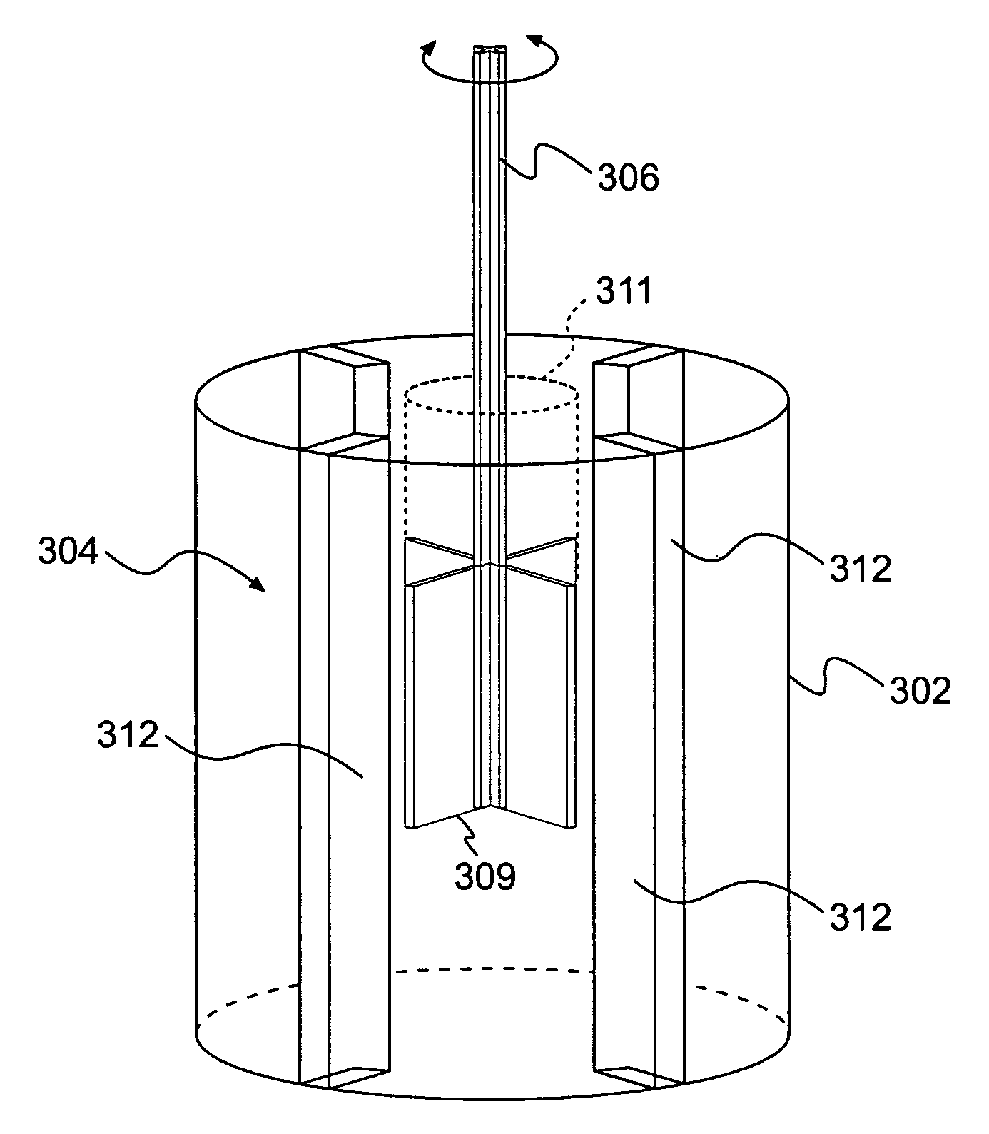
[0025]FIG. 3 depicts portions of a rheology measurement system 300 in accordance with an exemplary embodiment of the present invention. The system comprises a cylindrical measurement cell 302 that is used to house granular material to be measured.

[0026]The granular material to be measured (not shown) may contain grains (or “particles”) of a range of average size; in a preferred embodiment, the average grain size of material to be measured is in the range of about 10 micrometers to about 1 millimeter. The “average” particle size may, for example, refer to the mean size or the mode size according to the known statistical meaning of the words “mean” and “mode.” Moreover, in general, individual powder particles need not be equi-axed in shape, but may comprise platelet-like structures, elongated structures, a mix of structures, and other structures.

[0027]Measurements are performed with the aid of a rotating vane tool 306 introduced in cell 302 along the cylinder axis. The rotating vane t...


PUM


Abstract

A system for characterizing rheological properties of granular material. A cylindrical measurement cup containing granular material is subject to a uniform vibration induced by a vibration exciter at a user-determined frequency. At the same time, a rotation or an oscillation of a rotating vane tool is performed within the powder and a response measured. Baffles are affixed to the inner wall of the measurement cup to prevent slippage of the granular material during measurement. An energy imparted to the system from the vibration exciter can be measured by an accelerometer coupled to the measurement cup. When sufficient vibrational energy is supplied to the system, a powder contained therein achieves a particle “temperature” sufficient such that the powder behaves as an ergodic system. The visco-elastic properties of the ergodic powder can be reproducibly measured in accordance with known methodology used in molecular fluids, where the powder “temperature” can be varied by changing the vibration frequency or amplitude.

Description

BACKGROUND[0001]1. Field of the Invention[0002]The present invention relates generally to scientific instrumentation and in particular to applying rheology to the characterization of granular materials.[0003]2. Background of the Invention[0004]Knowledge of rheological properties of granular materials (also termed “powders”) such as foods, cosmetics, pharmaceuticals, paints, coatings, cements, and other materials is of paramount interest in the preparation and use of such materials. Physical characteristics of granular materials such as particle size, shape, size distribution, and hardness all affect the powder flow properties. Because of the inherent metastability of powders in relation to their flow properties, conventional rheometric analysis does not provide a reliable means for measuring powder behavior as described below.[0005]Properties of powders in their normal state are such that the flow behavior observed is unpredictable. These properties often depend on the details of gr...

Claims


Application Information

Patent Timeline
IPC IPC(8): B01F7/16B01F7/18B01F11/00B01F15/00G01N3/24G01N11/00G01N11/10G01N11/14G01N11/16G01N15/00G01N33/00
CPCB01F7/1675B01F7/18B01F11/008B01F11/0088B01F15/00207G01N11/14G01N11/16G01N2015/0096G01N2033/0091B63B21/38B01F27/86B01F27/90B01F31/44B01F31/445B01F35/213G01N11/00
Inventor MARCHAL, PHILIPPECHOPLIN, LIONELSMIRANI, NADIA
Owner WATERS INVESTMENTS
Why Eureka
Try Eureka