Contact coating of prostheses

a technology of contact coating and prosthesis, which is applied in the field of implantable devices or prostheses, can solve the problems of occlusion of conduits, thrombosis acute and subacute, and collapse of inner flaps or torn arterial linings,

Inactive Publication Date: 2005-12-06
BOSTON SCI SCIMED INC
View PDF11 Cites 108 Cited by
  • Summary
  • Abstract
  • Description
  • Claims
  • Application Information

AI Technical Summary

Benefits of technology

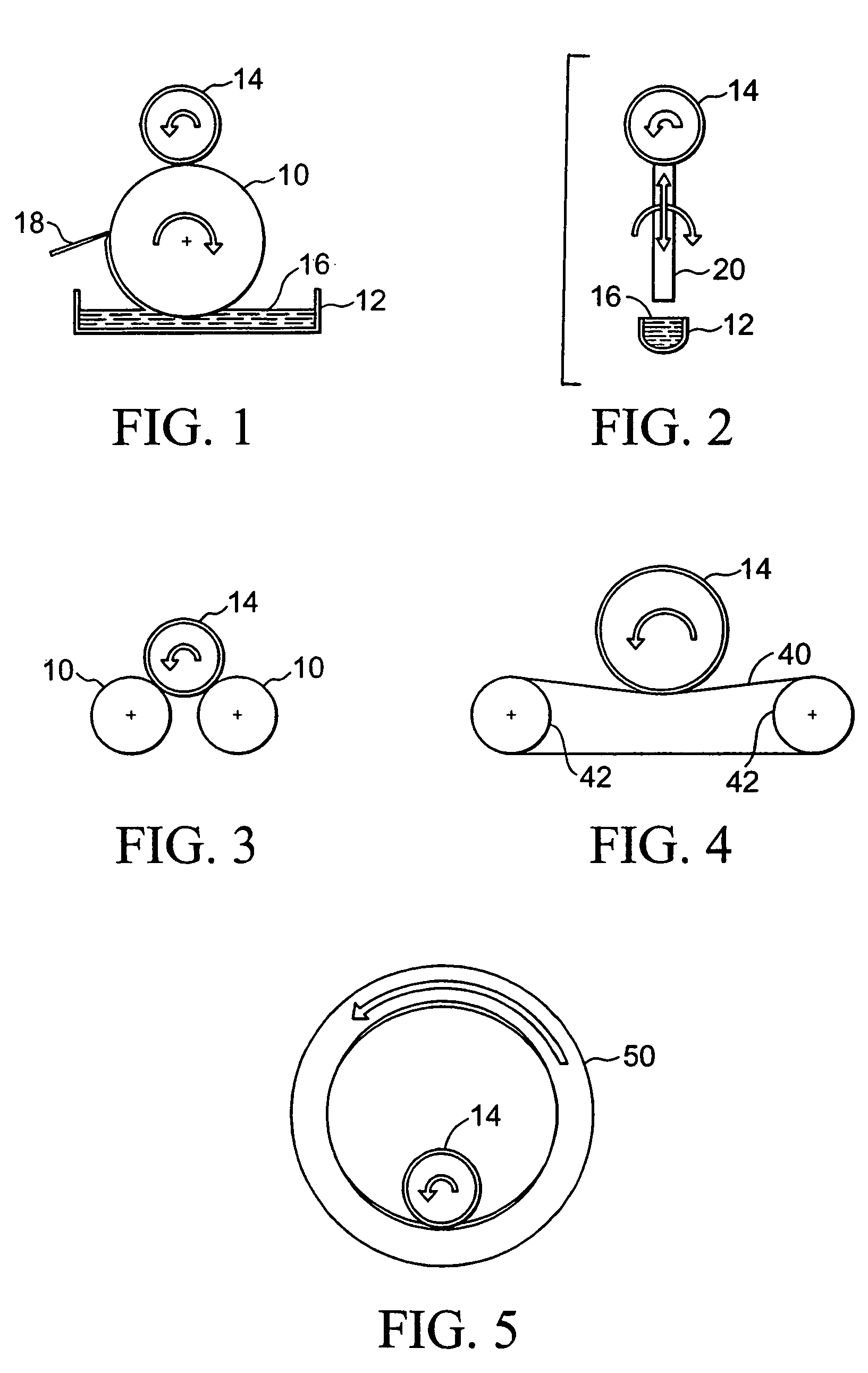
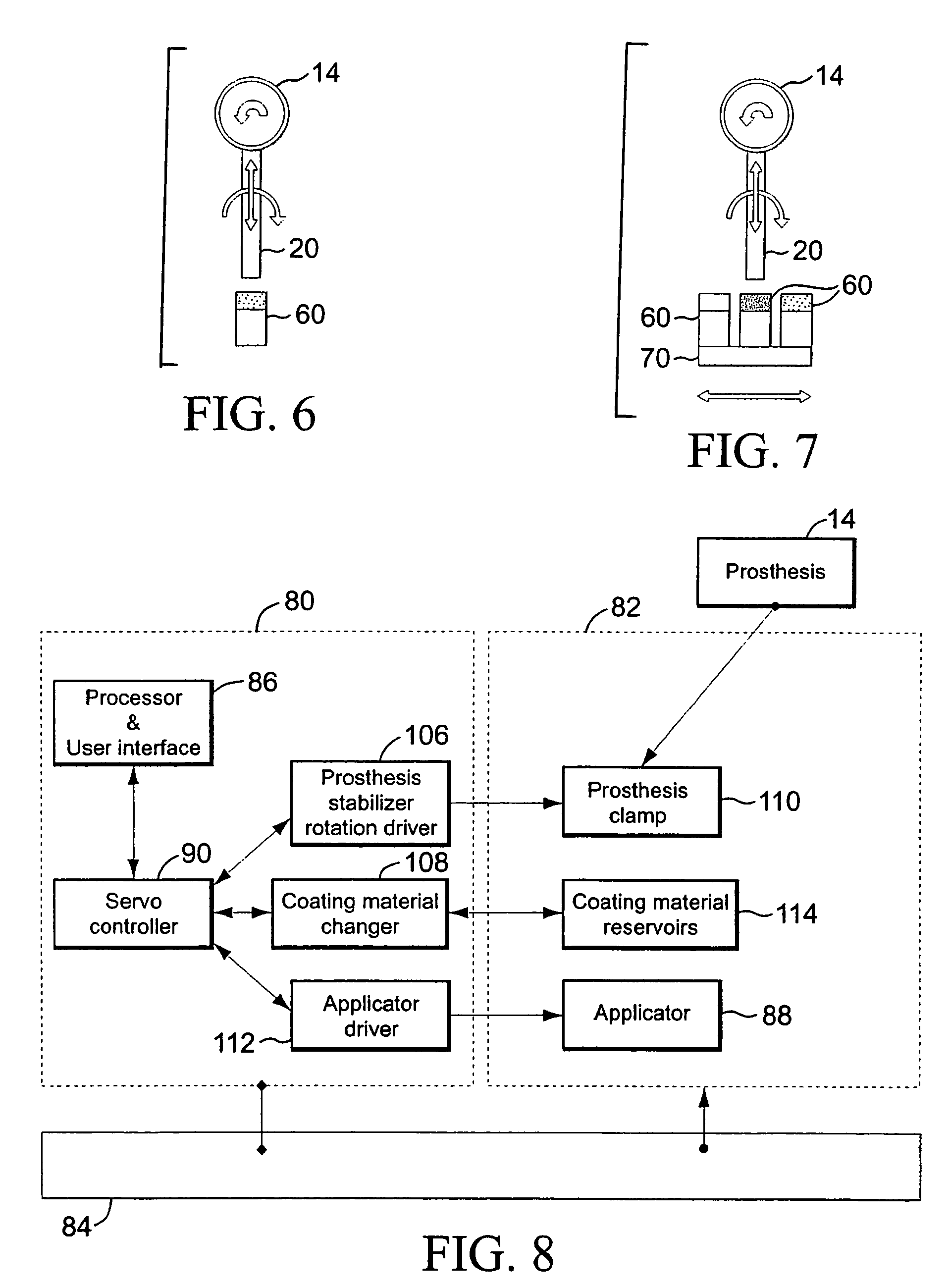
[0028]In accordance with the invention, a method of coating comprises (a) obtaining a prosthesis, (b) positioning an applicator in contact with the prosthesis, and (c) translating the applicator over the prosthesis, where translating applies a contact pattern of a coating material on the prosthesis. In one embodiment, the prosthesis is a stent. The stent can comprise a scaffolding network and gapped regions, whereby the applicator contacts the scaffolding network to avoid any significant application to the gapped regions. In one embodiment, the applicator is a roller. In one embodiment, the prosthesis is in contact with an exterior surface of the roller. In another embodiment, the prosthesis is in contact with an interior surface of the roller. In one embodiment, the roller contacts a reservoir comprising the coating material. In one embodiment, a wiper removes excess coating material from the roller prior to contacting the prosthesis. In one embodiment, the roller contacts a sponge comprising the coating material. In one embodiment, the applicator is at least two rollers positioned in contact with the prosthesis. In one embodiment, the applicator is a ribbon spooled around at least two rollers. In one embodiment, the applicator is a tampon. In one embodiment, the tampon contacts a sponge comprising the coating material. In one embodiment, the tampon contacts a cartridge comprising the coating material chosen from polymers, therapeutic agents, or mixtures thereof. In one embodiment, the method further comprises (d) moving the prosthesis in a direction opposite to the movement a applicator. In one embodiment, the coating material comprises materials chosen from polymers, therapeutic agents, or mixtures thereof.

Problems solved by technology

A problem associated with the above procedure includes formation of intimal flaps or torn arterial linings which can collapse and occlude the conduit after the balloon is deflated.
Percutaneous endovascular prosthetic stents were conceived in the late 1970's as a way to prevent both acute occlusion and late restenosis after catheter intervention, but initial clinical results of coronary stenting in 1987 were plagued by high (>20%) acute and subacute thrombosis and were restricted to use as “bailout” for threatened or acute vessel closure.
To provide an efficacious concentration to the treated site, systemic administration of such medication often produces adverse or toxic side effects for the patient.
Disadvantages of dip-coating and spray-coating methods include the inability to control the exact portions of the stent that come in contact with the coating.
Web-like defects are most prevalent in stents having tight patterns, for example coronary stents, such that the distance between the struts is very small.
This may result in depositing coating material on surfaces on which the coating is unwanted or undesirable.
Further, the coating may crack or break away when the implantable is removed from the implantation apparatus.
As the balloon is inflated and the stent is expanded into position, the coating may crack along the interface between the stent and the balloon.
These cracks may lead to a breaking away of a portion of the coating from the stent itself.
This, in turn, may affect the medicinal effectiveness of the coating, and negatively affect the entire medical procedure.
Another disadvantage of both dip-coating and spray-coating stems from a low-viscosity requirement for the polymer solution in which the stent is dipped or with which the stent is sprayed.
Thus, both dip-coating and spray-coating methods have imposed limitations in type and concentration of applied carriers.
In addition, coating the prosthesis can be achieved with such control such that the prosthesis can be coated in the operating room prior to insertion of the prosthesis into the patient, thus avoiding coating portions of the prosthesis or prosthesis handling apparatus, such as a catheter, where such a coating is not desirable.

Method used


Image

  • Contact coating of prostheses
  • Contact coating of prostheses
  • Contact coating of prostheses

Examples


Embodiment Construction

[0001]1. Field of the Invention

[0002]This invention relates generally to implantable devices or prostheses. More particularly, the invention is directed to an apparatus and method for coating a prosthesis using contact printing.

[0003]2. Definitions

[0004]The term “prosthesis” refers to any one of many medical coating applications including but not limited to coronary stents, peripheral vascular stents; abdominal aortic aneurysm (AAA) devices, biliary stents and catheters, TIPS catheters and stents, vena cava filters, vascular filters and distal support devices and emboli filter / entrapment aids, vascular grafts and stent grafts, gastro enteral tubes / stents, gastra enteral and vascular anastomotic devices, urinary catheters and stents, surgical and wound drainings, radioactive needles and other indwelling metal implants, bronchial tubes and stents, vascular coils, vascular protection devices, tissue and mechanical prosthetic heart valves and rings, arterial-venous shunts, AV access gra...


PUM

PropertyMeasurementUnit
thicknessaaaaaaaaaa
thicknessaaaaaaaaaa
areaaaaaaaaaaa

Abstract

A method and apparatus for coating prostheses via contact patterning with an applicator. Applicators can include rollers, tampons, and ribbons. Coating materials include a variety of substances including polymers and therapeutic agents.

Description

DESCRIPTION OF THE INVENTION[0001]1. Field of the Invention[0002]This invention relates generally to implantable devices or prostheses. More particularly, the invention is directed to an apparatus and method for coating a prosthesis using contact printing.[0003]2. Definitions[0004]The term “prosthesis” refers to any one of many medical coating applications including but not limited to coronary stents, peripheral vascular stents; abdominal aortic aneurysm (AAA) devices, biliary stents and catheters, TIPS catheters and stents, vena cava filters, vascular filters and distal support devices and emboli filter / entrapment aids, vascular grafts and stent grafts, gastro enteral tubes / stents, gastra enteral and vascular anastomotic devices, urinary catheters and stents, surgical and wound drainings, radioactive needles and other indwelling metal implants, bronchial tubes and stents, vascular coils, vascular protection devices, tissue and mechanical prosthetic heart valves and rings, arterial-...

Claims


Application Information

Patent Timeline
Patent Type & Authority Patents(United States)
IPC IPC(8): A61F2/00A61F2/86A61L31/10A61L31/14A61L31/16
CPCA61L31/10A61L31/14A61L31/16B05D1/28A61F2/86A61F2250/0067B05D7/22B05D2254/02B05D2254/04
Inventor SHEKALIM, AVRAHAMTEICHMAN, EYAL
Owner BOSTON SCI SCIMED INC
Why Eureka
Try Eureka