Heated trough for molten metal

a technology for conveying troughs and molten metals, which is applied in the direction of manufacturing converters, manufacturing tools, furniture, etc., can solve the problems of uneven heating, difficult maintenance, and hot spots of heat exchangers

Inactive Publication Date: 2005-12-13
NOVELIS INC
View PDF13 Cites 56 Cited by
  • Summary
  • Abstract
  • Description
  • Claims
  • Application Information

AI Technical Summary

Benefits of technology

[0011]In a further embodiment of the invention there is provided a method for heating molten aluminum in a trough for conveying metal wherein the trough comprises an outer shell defined by a bottom wall and two side walls, an insulating layer filling the outer shell and a conductive U-shaped refractory trough body for carrying molten metal, the trough body being embedded in the insulating layer and wherein heat is provided by one or more radiant heaters embedded in the tough lining adjacent the conductive U-shaped refractory trough but spaced apart from the trough body, to provide an air gap between the heating element and the trough body.

Problems solved by technology

Such heaters tend to form hot spots and uneven heating due to the difficulty in ensuring good contact with the surrounding refractory.
They can be difficult to maintain because of a tendency get stuck by metal impregnation or expansion of the element shell.
However, heaters radiating to the surface of a molten metal are overall inefficient because of the low emissivity of the surface.
There is a common tendency for impurities, or inclusions, to form in molten metal as it travels down the trough, which is made more serious for troughs heated from above (top-heated).

Method used


Image

  • Heated trough for molten metal
  • Heated trough for molten metal
  • Heated trough for molten metal

Examples


Embodiment Construction

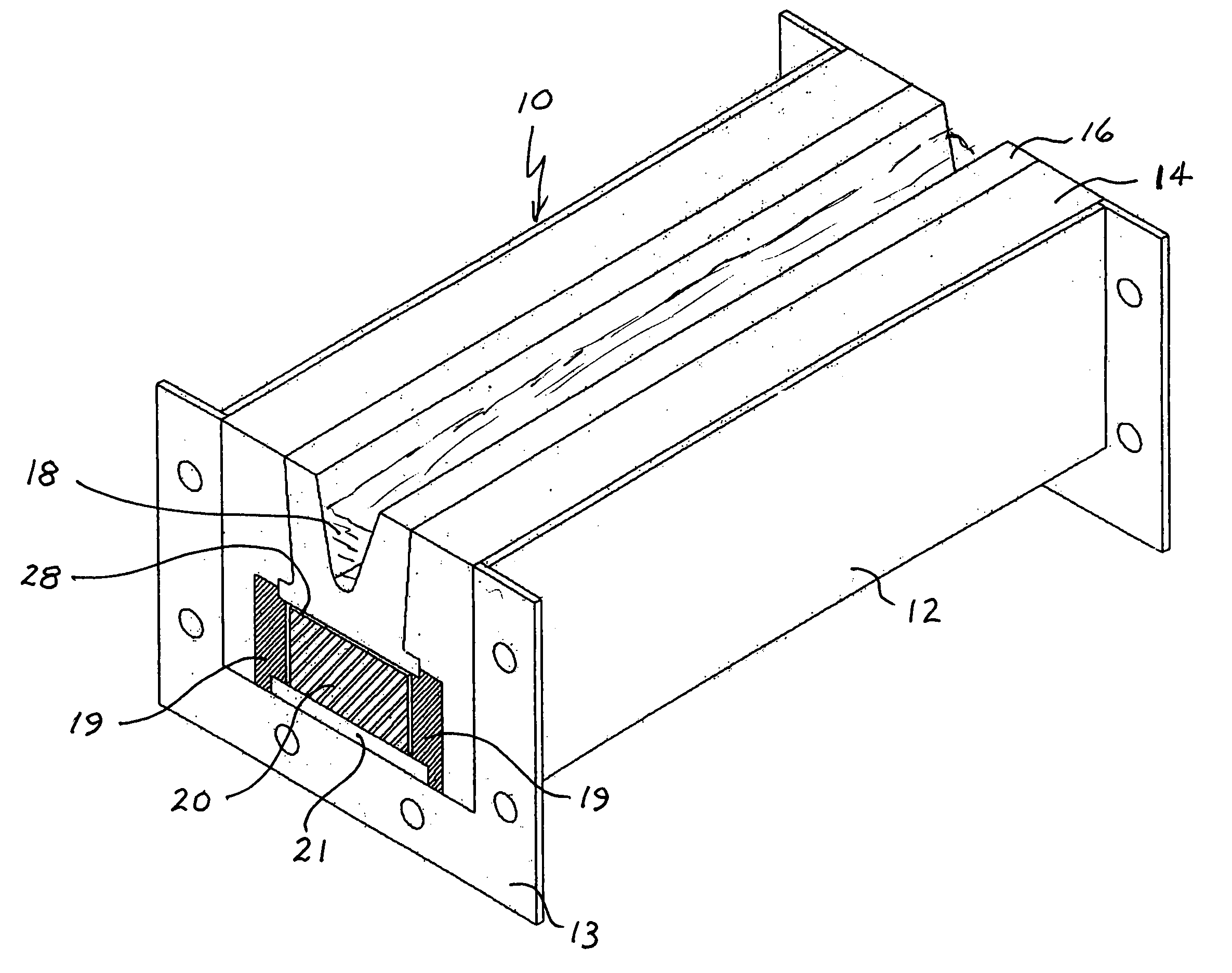
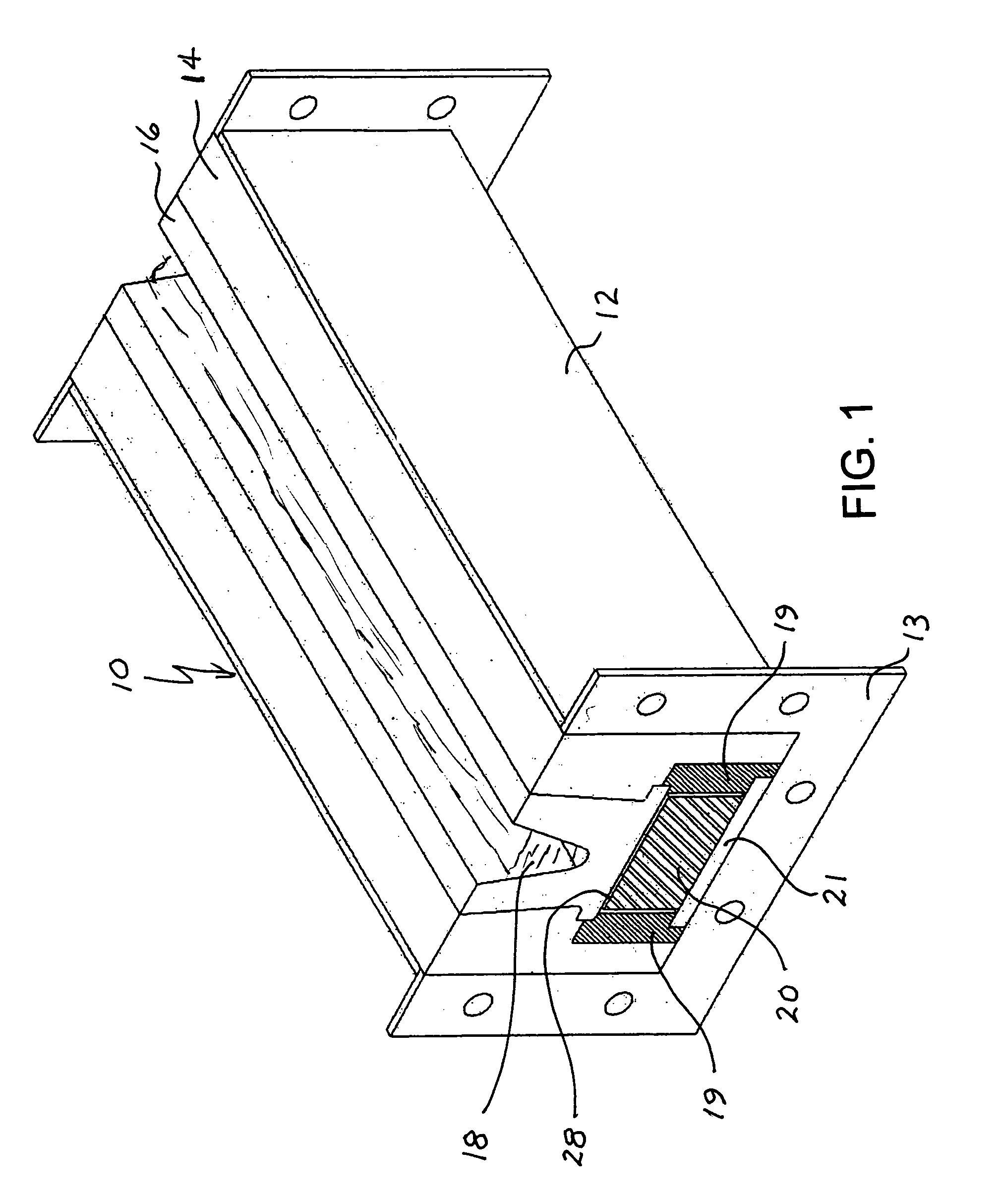
[0017]FIGS. 1 and 2 show a perspective and cross-sectional view of a heated trough according to the present invention. With reference to these figures, trough 10 comprises an outer shell 12, which can be made of steel or other suitable materials well known in the art, and end plates 13 suitable for connecting trough sections together or for attaching to other parts of the metal handling system. Inside the outer shell 12 is a layer of insulation 14 and resting within the insulation 14 is a U-shaped trough body 16 for carrying molten metal 18. The trough body 16 is generally highly conductive and resistant to corrosion from the molten metal and can be made of a dense refractory such as, for example, silicon carbide or graphite. The layer of insulation can consist of a single type of insulation, or may be graded from inner to outer surface with different types in sublayers. The insulation is typically an alumino-silicate refractory fibrous or pourable insulating refractory.

[0018]The tr...


PUM

PropertyMeasurementUnit
distanceaaaaaaaaaa
voltagesaaaaaaaaaa
voltagesaaaaaaaaaa

Abstract

A trough is described for carrying molten metal, comprising an outer shell defined by a bottom wall and two side walls, an insulating layer filling the outer shell and a conductive U-shaped refractory trough body for carrying molten metal, the trough body being embedded in the insulating layer. At least one heating element is positioned in the insulating layer, adjacent to but spaced apart from the trough body, to provide an air gap between the heating element and the trough body.

Description

FIELD OF THE INVENTION[0001]The invention generally relates to apparatus for conveying molten metal, and more specifically molten aluminum in aluminum casting processes.BACKGROUND OF THE INVENTION[0002]In molten metal processing, troughs are generally used to convey the molten metal from the melting furnace to various process devices, such as casting moulds, analyzers, etc. Where there is ample metal flow, there is sufficient sensible heat in the molten metal to compensate for heat losses via the trough. However, in low metal flow situations, or long trough runs, some form of trough heating is required to prevent excessive metal heat loss.[0003]U.S. Pat. No. 3,494,410 (Birchill et al) discloses a generic heated trough with provision for heating from any side, but without any detail as to how to achieve efficient thermal control.[0004]U.S. Pat. No. 4,345,743 (Sivilotti) teaches an adiabatic tubular discharge conduit including a refractory lining for containing the molten metal and en...

Claims


Application Information

Patent Timeline
Patent Type & Authority Patents(United States)
IPC IPC(8): B22D35/06B22D41/01
CPCB22D35/06B22D41/01B22D35/04
Inventor TINGEY, JOHN S.SALEE, DAVID A.BOWLES, WADE LEE
Owner NOVELIS INC
Why Eureka
Try Eureka