Implantable orthopedic prosthesis with textured polymeric surfaces

a polymer and orthopedic technology, applied in the field of orthopedic prostheses, can solve the problems of unwelcome problems, weakening of the bond between the bone and the implant, and subsidence of the implant affixed with cement, so as to reduce the degree of bone resorption and enhance the bonding properties

Inactive Publication Date: 2005-12-13
ZIMMER INC
View PDF10 Cites 22 Cited by
  • Summary
  • Abstract
  • Description
  • Claims
  • Application Information

AI Technical Summary

Benefits of technology

[0014]Prostheses of the present invention are intended to be press-fit into a prepared bone cavity. Preferably then, no cement is used. As one important advantage of the present invention, the textured or porous surface is not applied as a coating to the prosthesis or fabricated during the formation of the polymer or polymeric structure. Rather, any one of or combination of several surface texturing techniques is used to form the textured or porous surface. These techniques include grit blasting, laser texturing, and machining (such as cutting, drilling, knurling, milling, and combinations of these techniques). Preferably, ultra high molecular weight polyethylene, UHMWPE, is used to form the polymeric components.
[0015]The porous surface layer can also be coated, doped, or the like with another media to enhance bone bonding properties between the prosthesis and surrounding bone. Plasma sprayed titanium, hydroxyapatite, or growth agents (such as BMPs), for example, can be added or applied to the bone engaging surface.
[0016]One embodiment of the present invention includes an orthopedic implant and, specifically, a femoral hip stem and accompanying prosthetic acetabulum. The femoral hip stem is formed of a metallic core with a polymeric proximal body. The acetabulum is formed entirely of polymer. The outer surface or bone engaging surface of the proximal body and acetabulum are texturized with one or more of the noted techniques. These surfaces are adapted to induce bone growth into the surface.
[0017]In this embodiment, since the proximal body and acetabulum are entirely formed of polymer, the elastic modulus of the implant more closely matches the natural elastic modulus of surrounding bone. The minimization of the elastic modulus mismatch between the implant and bone reduces the degree of bone resorption consistent with traditional metallic implants.
[0018]Another embodiment of the present invention includes an orthopedic implant and, specifically, an all-polymeric tibial articulating component

Problems solved by technology

As one example, the bond between the bone and implant can weaken over time and cause complications.
Further, implants affixed with cement can subside after the cement hardens and also cause unwanted problems.
As a result of this disparity in elastic modulus, bone tissues are likely fractured or crashed because of the micro-motion and press-fit at the bone-implant interface.
Conventional press-fit prosthesis often provide inconsistent long-term fixation to bone because of inadequate interfacial osteogenesis (i.e., bone growth directly to the outer surface of the implant).
If the original pore size of the implant is too small or if the porous structure has been distorted by applied loads, one or more of the above sequence of events can be interrupted or hampered.
In particular, implants formed from metal and ceramic can have a distinct disadvantage.
For example, the modulus of metals and ceramics is so high that the implants do not sufficiently deform under the applied loads.
The implant thus does not adequately spread load to surrounding bone (known as “stress-shielding”), and resorption can occur.
Further, bone spicules in these porous implants do not experience sufficient loads to thicken.
Bone trabeculae in the higher modulus porous materials tend to thin, a situation that also can lead to resorption.
Not surprisingly, much effort has been directed toward engineering polymeric coatings for use with implants.

Method used


Image

  • Implantable orthopedic prosthesis with textured polymeric surfaces
  • Implantable orthopedic prosthesis with textured polymeric surfaces
  • Implantable orthopedic prosthesis with textured polymeric surfaces

Examples


Embodiment Construction

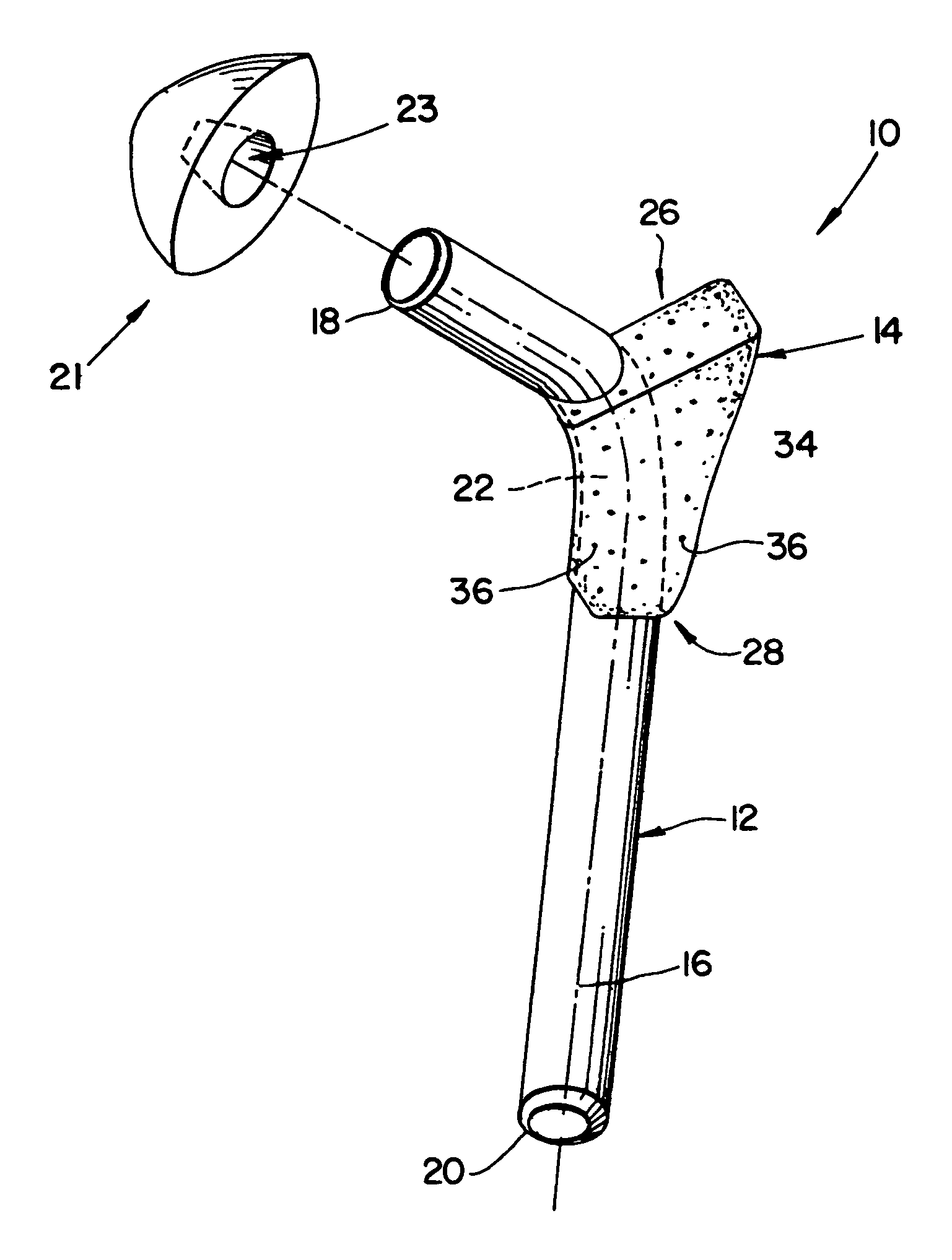
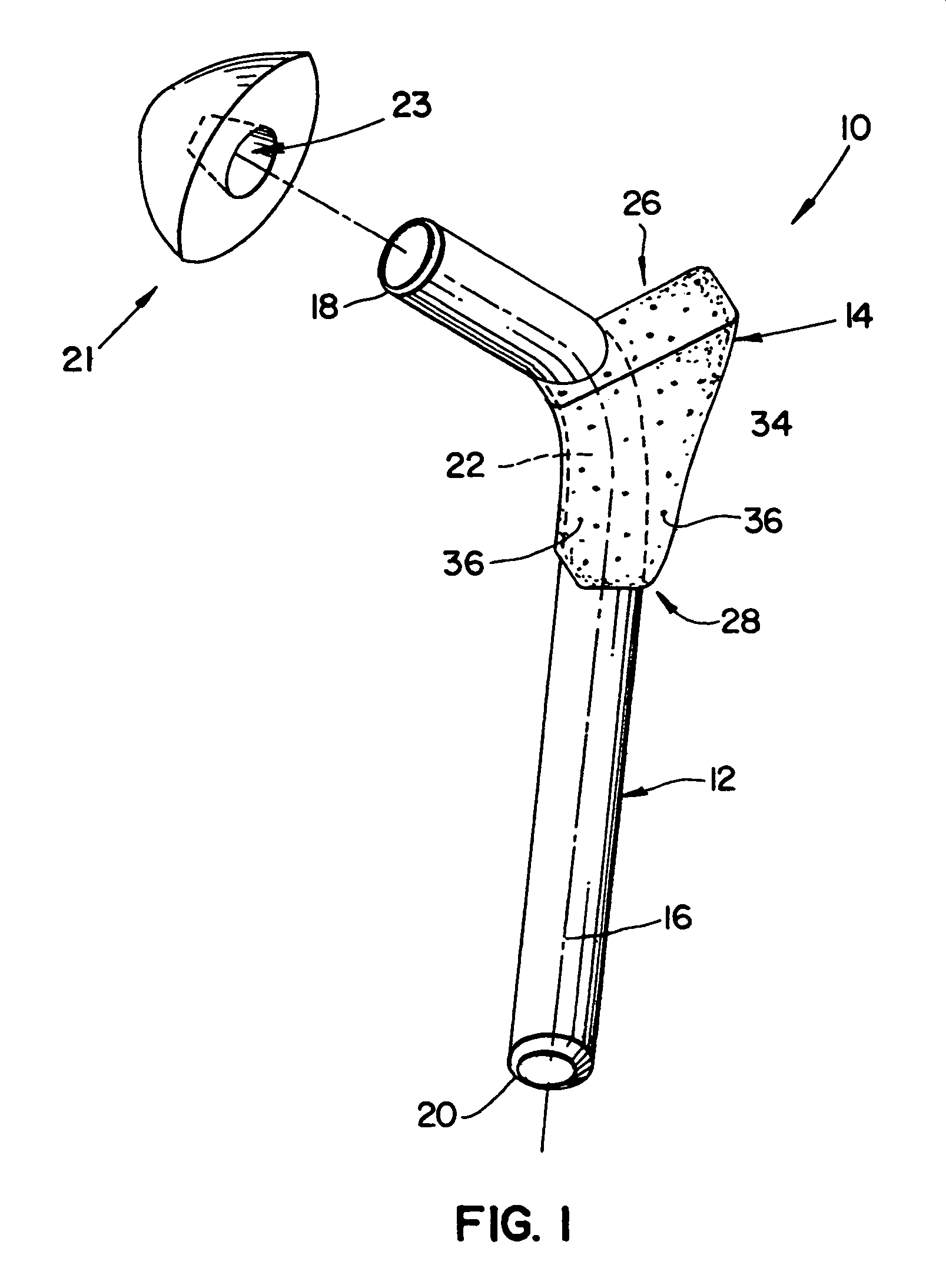
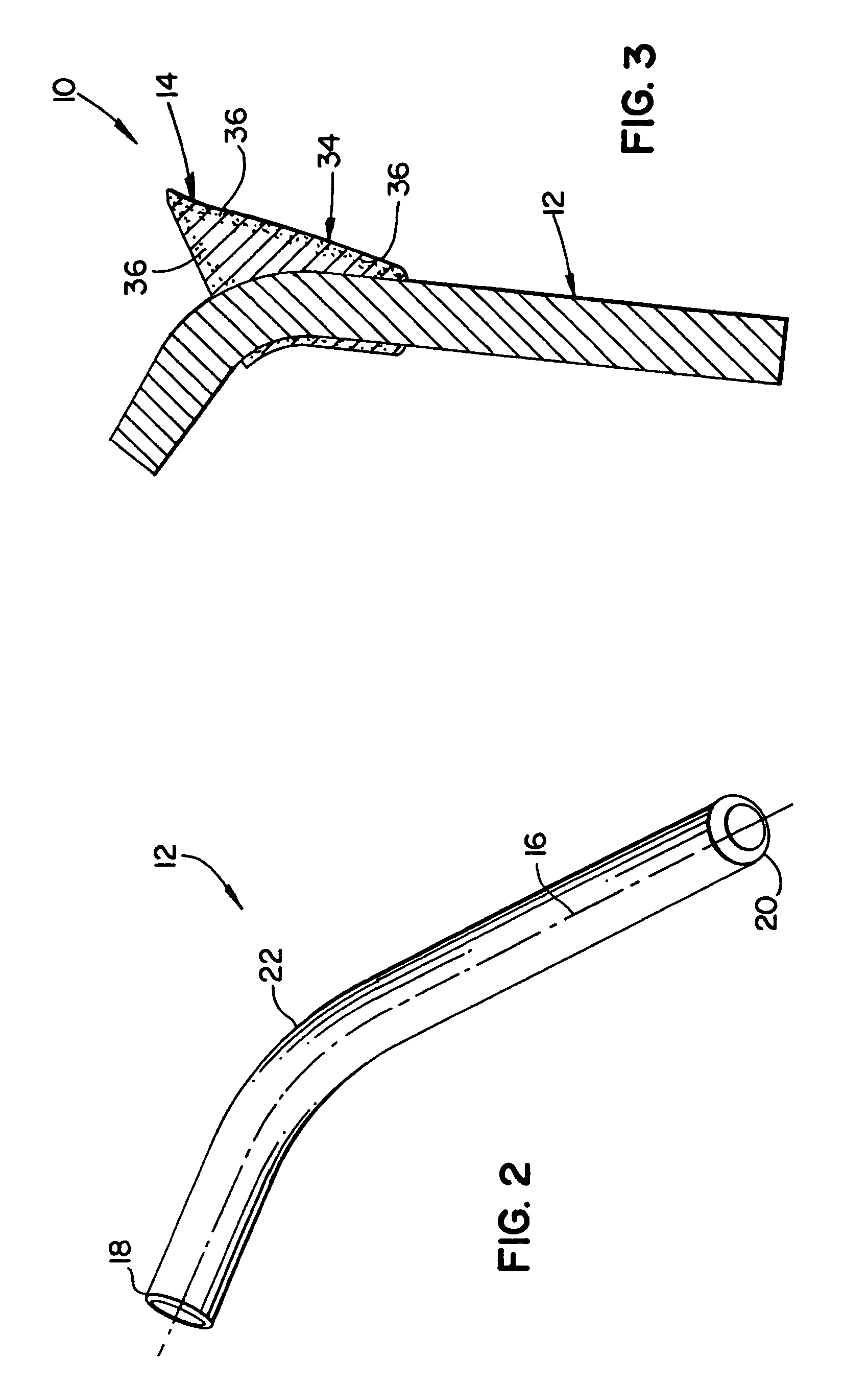
[0026]Looking to FIG. 1, an implantable orthopedic femoral hip implant 10 is shown. Implant 10 includes a solid metal core 12 and a proximal body 14 formed entirely of a polymer. The metal core 12 is formed as an elongated shaft or body and extends from a first or proximal end 18 to a second or distal end 20. A contoured, longitudinal axis 16 extends down the center of the shaft.

[0027]Looking also to FIG. 2, the first end 18 is tapered and adapted to matingly engage and connect to a femoral bait or head 21. The head 21 includes a tapered bore or recess 23 adapted to receive and engage first end 18.

[0028]The second end 20 is rounded to facilitate insertion into the intramedullary canal at the proximal end of a femur. Between the first and second ends 18 and 20, respectively, the metal core 12 has a proximal portion 22 that connects to the proximal body 14. The proximal portion 22 may have a particular surface finish and geometry for connecting or bonding with the proximal body 14. A ...


PUM

PropertyMeasurementUnit
thicknessaaaaaaaaaa
pore diameteraaaaaaaaaa
porosityaaaaaaaaaa

Abstract

Implantable prostheses fully or partially formed of polymer having a textured or porous outer surface. The surface permits and encourages osteogenesis into the prosthesis and enables it to become firmly and permanently anchored into surrounding bone. The prostheses include a femoral hip stem formed of a metallic core and a polymeric proximal body with a textured or porous surface formed from a laser texturing, machining, or grit blasting.

Description

FIELD OF THE INVENTION[0001]The disclosure herein generally relates to implantable orthopedic prostheses and, more particularly, to polymeric implants with textured or porous outer surfaces adapted to engage bone.BACKGROUND OF THE INVENTION[0002]Two main techniques are commonly used to fix an implantable orthopedic prosthesis to bone: Techniques using bone cement, and techniques pressing the implant into position. During the former technique, bone cement (typically PMMA, or polymethylmethacrylate) is applied in a dough-like state as a grouting agent between the bone and the implant. The cement flows around the contours of the osteotomy and the implant and into the interstices of cancellous bone. Upon hardening, the cement forms a mechanical interlock between the bone and the outer surface of the implant. In effect, no bone growth into the surface of the implant occurs since cement is used to hold the implant in place.[0003]Although bone cement gives good initial fixation, it has som...

Claims


Application Information

Patent Timeline
Patent Type & Authority Patents(United States)
IPC IPC(8): A61F2/00A61F2/30A61F2/34A61F2/36A61F2/38A61L27/04A61L27/16A61L27/56
CPCA61F2/30734A61F2/30771A61F2/34A61F2/367A61F2/389A61L27/04A61L27/16A61L27/56C08L23/06A61F2/30767A61F2/3094A61F2/36A61F2/3662A61F2002/30013A61F2002/30112A61F2002/30113A61F2002/30133A61F2002/30158A61F2002/30224A61F2002/30322A61F2002/30332A61F2002/30377A61F2002/30736A61F2002/30828A61F2002/30831A61F2002/30892A61F2002/30906A61F2002/3097A61F2002/3429A61F2002/3611A61F2002/3625A61F2002/365A61F2220/0033A61F2230/0004A61F2230/0006A61F2230/0015A61F2230/0026A61F2230/0069A61F2250/0024A61F2250/0026A61F2310/00011A61F2310/00023A61F2310/00029A61F2310/00407A61F2310/00796A61F2310/00976A61F2002/30011A61F2002/30367
Inventor ZHU, MENGKE
Owner ZIMMER INC
Why Eureka
Try Eureka