
Method and apparatus for removing foaming contaminants from hydrocarbon processing solvents

Inactive Publication Date: 2005-12-13
MPR SERVICES INC
View PDF15 Cites 15 Cited by
  • Summary
  • Abstract
  • Description
  • Claims
  • Application Information

AI Technical Summary

Benefits of technology

[0022]It is an object of the present invention to provide a method and apparatus for improving the mass transfer capabilities in hydrocarbon processing.
[0023]It is another object of the present invention to provide an improved method and apparatus for removing foam contaminants from hydrocarbon fluid processing solvents.
[0025]It is another object of the present invention to provide a method and apparatus for removing foam contaminants from hydrocarbon fluid processing solvents, wherein the foam structure is modified to reduce solvent content and to make the foam more manageable.
[0033]In accordance with another aspect of the present invention, the foam is coarsened as it is pushed, whereby the foam becomes drier and easier to shear.
[0036]In accordance with another aspect of the present invention, the step of introducing gas into the column at a second location further comprises the step of removing gas from the column at a location above a surface level of the liquid and educting the gas with the flow of solvent taken from the column. The foam is coarsened as it is pushed, whereby the foam becomes drier and easier to shear. The contaminated solvent comprises immiscible liquid, which immiscible liquid is separated from the solvent as the solvent is introduced into the column.
[0040]In accordance with still another aspect, the present invention further comprises the step of coarsening the foam as it is pushed, whereby the foam becomes drier and easier to shear.

Problems solved by technology

Processing removes undesirable components from the gas, such as moisture or sour contaminants.
Reusing the solvent is desirable for environmental reasons (disposal of the solvent is both difficult and expensive) and also because replacing the solvent is expensive.
Another contaminant in the gas is carbon dioxide.
This occurs if the gas rate through the contactor is too high or if the solvent contains relatively high concentrations of foaming contaminants.
Foaming of the solvent is undesirable because foaming leads to a loss of efficiency of the contactor, causes contamination of the gas with the solvent, and results in the loss of the expensive solvent.
The prior art systems suffered from several problems.
Disposal of the used filters can be expensive due to environmental concerns.
In addition, the filters themselves are expensive.
It is difficult to select a proper type of filter for the particular foaming contaminant present in the solvent.
Typically, the particular type of foaming contaminant is unknown, resulting in guess work as to the particular filter which is to be used.
The presence of foaming contaminants reduces the efficiency of the gas-liquid contactor.
The quantity of mass transferred is adversely affected even if the contactor does not exhibit signs of foaming (such as foam production at the top of the contactor or variations in the pressure at the gas outlet).
However, the contactor efficiency is reduced even by a quantity of foaming contaminants that is too small to cause detectable foaming.
Thus, even if foaming is undetected by the operator, the efficiency is likely to be relatively low.
Furthermore, the addition of anti-foaming agents does not reduce the amount of foaming contaminants.
Consequently, the foaming contaminants continue to adversely affect the contactor efficiency.
Compressors are expensive and can be bulky.

Method used


Image

  • Method and apparatus for removing foaming contaminants from hydrocarbon processing solvents
  • Method and apparatus for removing foaming contaminants from hydrocarbon processing solvents
  • Method and apparatus for removing foaming contaminants from hydrocarbon processing solvents

Examples


Embodiment Construction

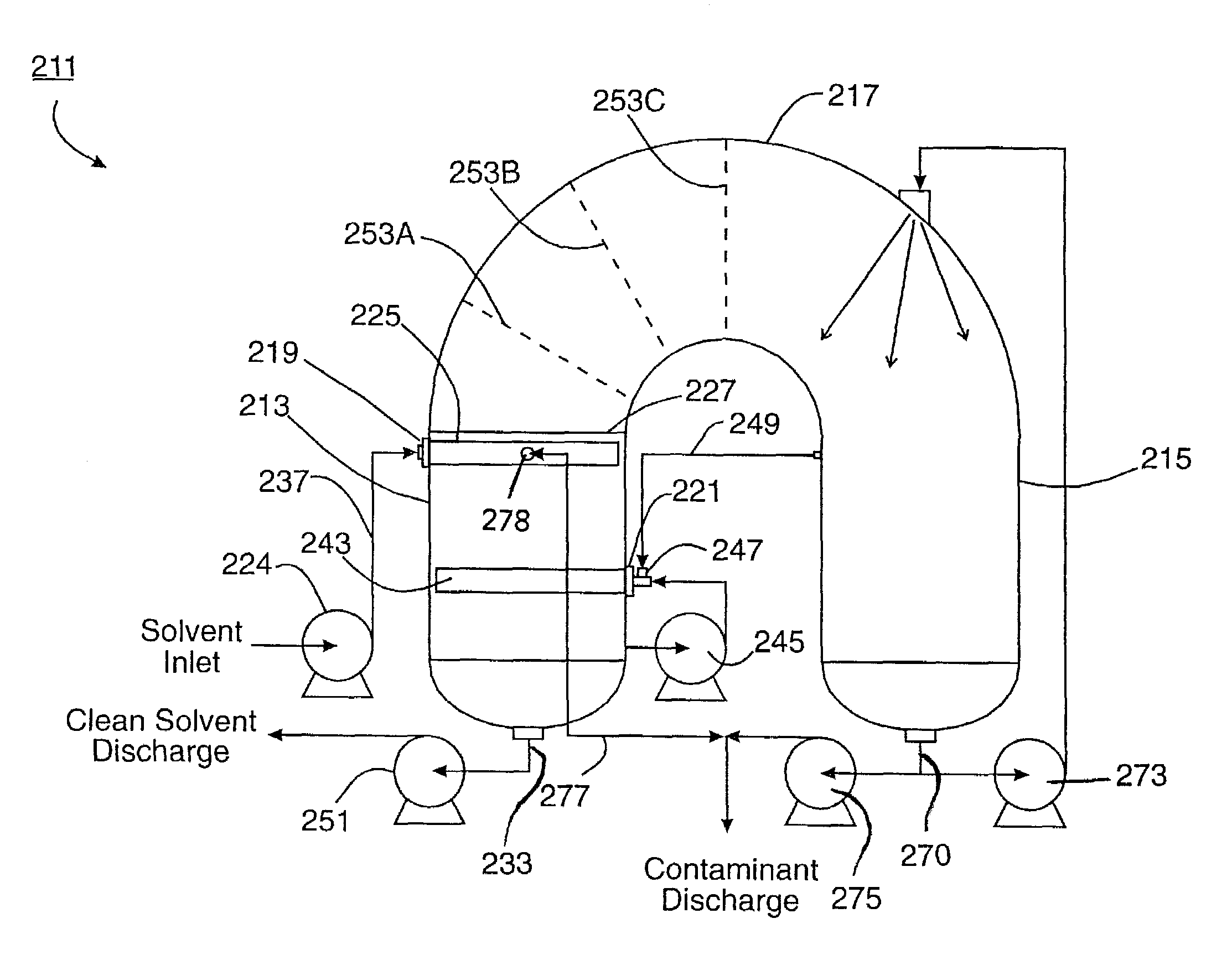
[0055]The present invention is used to remove contaminants, such as surfactants, from solvent that is in turn used to process hydrocarbon gas (such as natural gas). A predecessor system and method was disclosed in my earlier U.S. Pat. No. 6,080,320. The complete disclosure of U.S. Pat. No. 6,080,320 is incorporated by reference herein.

[0056]Examples of hydrocarbon gas processing units include dehydration units and sweetening units. The present invention can also be used on solvents that are used to process hydrocarbon liquids.

[0057]Dehydration units and sweetening units have solvent recycling equipment. The solvent recycling equipment takes the rich solvent and removes the moisture or sour contaminants to produce lean solvents.

[0058]The foam remover apparatus 211 of the present invention can be installed and operated in conjunction with the solvent recycling equipment. As the solvent circulates through the gas-liquid contactor, it takes up contaminants (for example, moisture or sour...


PUM

PropertyMeasurementUnit
Flow rateaaaaaaaaaa
Distanceaaaaaaaaaa

Abstract

A column of solvent containing foaming contaminants is provided. Gas is educted into the solvent in the column so as to generate foam in the column. The gas is educted into the column independently of the input flow of solvent into the solvent using a pumparound arrangement with the solvent. Foam generation continues so as to push the foam up in the column, wherein much of the solvent that is in the foam is allowed to drain back down into the column. The foam passes through concentrators which increase the residency time of the foam in the column to further dry the foam and to create larger bubbles. The drier foam is pushed out of the column and into a container. The foam is broken up into gas and the liquid foaming contaminants. The gas is recirculated for injection into the column even after foaming has stopped. The foaming contaminants are concentrated at the surface level of the solvent in the column. These contaminants are removed from the column. A liquid separator separates immiscible liquids, such as oil, from the solvent.

Description

[0001]This is a divisional application of application Ser. No. 09 / 794,286, filed Feb. 27, 2001 Now U.S. Pat. No. 6,602,423.FIELD OF THE INVENTION[0002]The present invention relates to apparatuses and methods for removing contaminants that can cause foaming in solvents that are used to process hydrocarbons such as natural gas.BACKGROUND OF THE INVENTION[0003]Hydrocarbon gas is frequently processed before storage, transportation through a pipeline or use. Processing removes undesirable components from the gas, such as moisture or sour contaminants.[0004]Processing gas to remove moisture is referred to as dehydration. Hydrocarbon gas containing moisture is typically dehydrated by exposing it to the solvent triethylene glycol. The moisture is removed from the hydrocarbon gas in order to increase the heating value of the gas and to reduce the condensation of free liquid water during transportation or storage. The removal of the moisture also reduces the formation of gas hydrates that fou...

Claims


Application Information

Patent Timeline
IPC IPC(8): B01D17/035B03D1/02B03D1/24
CPCB03D1/02B03D1/24B03D1/1462B03D1/1481B03D1/1412
Inventor VON PHUL, STEPHEN A.
Owner MPR SERVICES INC
Learn More