Stray light correction method for imaging light and color measurement system

a correction method and light technology, applied in the field of stray light correction method for imaging light and color measurement, can solve the problems of stray light contributing to inaccurate relative light levels for a specific filter, measurement of light levels in darker regions of objects to be higher than they actually are, and particular color coordinates are not accurate at that particular location, so as to eliminate stray light effect, increase the gray level value, and eliminate the effect of stray light

Active Publication Date: 2005-12-13
RADIANT ZEMAX
View PDF8 Cites 379 Cited by
  • Summary
  • Abstract
  • Description
  • Claims
  • Application Information

AI Technical Summary

Benefits of technology

[0018]Software is employed to automatically correct the stray light when an image is recorded using a solid-state light detector array. Correction values for various solid-state light detector array measurement systems (i.e., CCD, lens, and filter combinations) are stored in the software. By entering the specific solid-state light detector array system used to record the image, the corresponding correction value is automatically provided. Once an image is recorded, the gray level value at each pixel of the image is subtracted with the correction value to eliminate the stray light effect.
[0019]A first order correction to the stray light assumes that the stray light is uniformly scattered across the entire solid-state light detector array and the amount thereof is proportional to the light incident through the lens onto the solid-state light detector array. Consequently, a uniform increase of gray level value is resulted at each pixel of the solid-state light detector array. Therefore, by subtracting the measured gray level value with a unique value (correction value), the stray light effect can be eliminated. This first order correction method may yield accurate measurement results in cases where the object being measured consists of smooth varying luminance levels or many small areas of high and low luminance levels.
[0020]For measurements where the object being measured consists of larger areas of high and low luminance levels that are not smoothly varying, it is necessary to use several unique correction values for various regions of the object being measured because the stray light will not be uniformly scattered across the entire solid-state light detector. In this scenario, different areas of the solid-state light detector experience different levels of increased gray level value from stray light, and therefore different unique correction values need to be subtracted from different areas of the solid-state light detector in order to eliminate the stray light effect.

Problems solved by technology

This stray light causes an inaccuracy when a charge coupled device is used to make quantifiable color, illuminance, or luminance measurement.
While measuring illuminance or luminance, if the object being measured is highly non-uniform such as the checkerboard pattern or an automotive headlamp beam pattern, the stray light will tend to cause the measured light levels in darker regions of the object to be higher than they actually are.
Again, if the object is significantly non-uniform while being viewed through one or more of the filters, stray light may contribute to inaccurate relative light levels for a specific filter.
Since color coordinates are computed from the relative light levels of the matching filters, if the measurement is too high at a given location for a specific filter due to stray light, the particular color coordinate is not accurate at that particular location.
But due to stray light, some of the blue light may land on the charge coupled device corresponding to the red region of the object.
This results in an inaccurate color coordinate for the red region because the measured value for the blue filter is too high.

Method used


Image

  • Stray light correction method for imaging light and color measurement system
  • Stray light correction method for imaging light and color measurement system
  • Stray light correction method for imaging light and color measurement system

Examples


Embodiment Construction

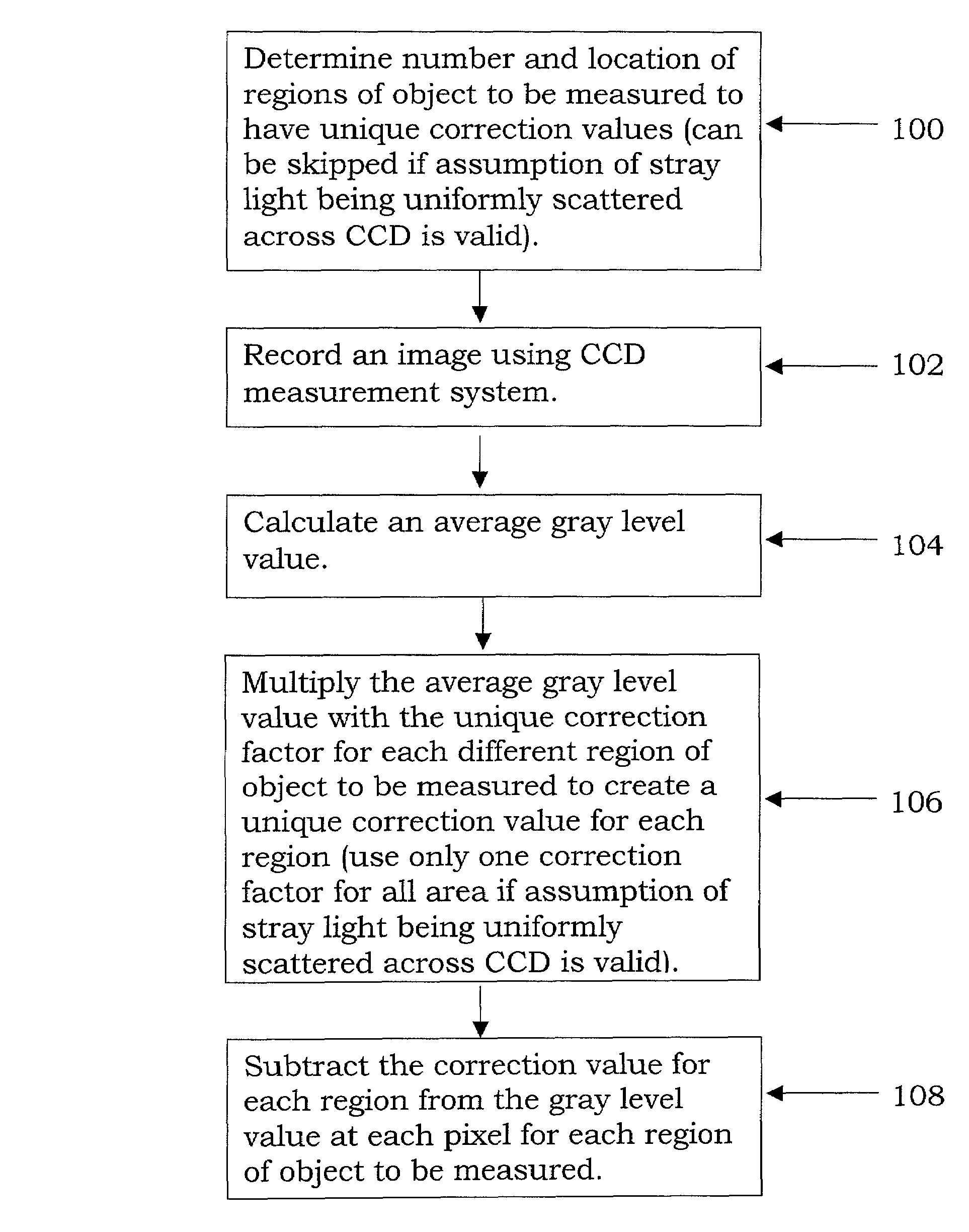
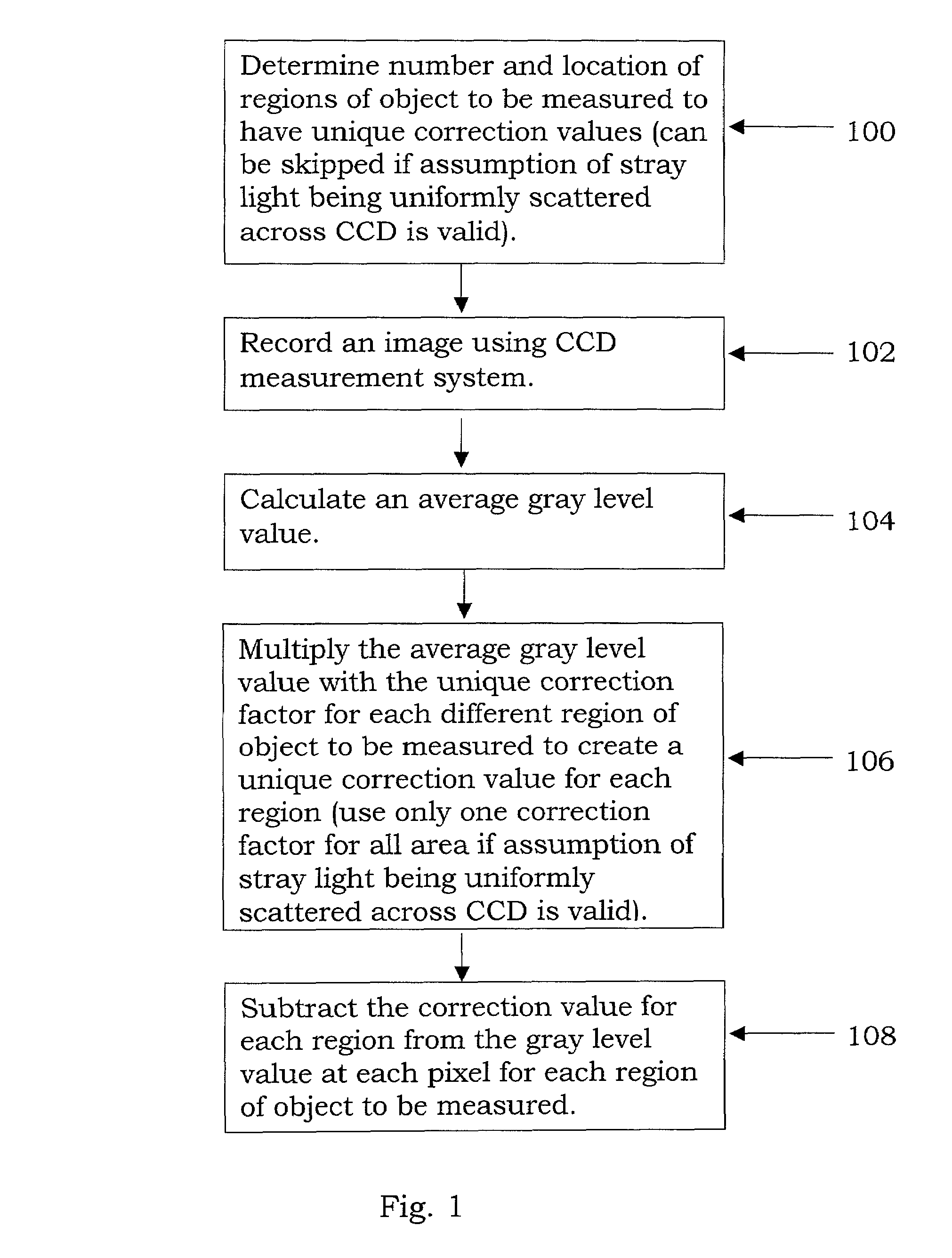
[0024]By way of background, to eliminate the stray light effect, an assumption is made according to the characteristics and the sources of the stray light in the present invention. The assumption comprises that the amount of stray light is directly proportional to the brightness of light incident on the solid-state light detector array, that is, the average gray level value measured by the solid-state light detector array. Because the stray light is partially caused by the lens and partially caused by the optional elements in the imaging light and color meter used to modify the spectral power distribution of incoming light for each instance of irradiation of the solid-state light detector array in a single color measurement, the amount of stray light is dependent on both the lens and the optical elements. Examples for the optical elements include a plurality of filters, a single tunable color filter, a plurality of tunable color filters, an interferometer, an interference grating, a...


PUM


Abstract

A stray light correction method for image light and color measurement system, uses a solid-state light detector array such as a charge-coupled device to record an image, so that a gray level value for each pixel of the solid-state light detector array is obtained. An average gray level value of the solid-state light detector array is calculated based on the gray level value for each pixel. The average gray level value is further multiplied with a stray light factor to obtain a correction value. The gray level value of each pixel is then subtracted with the correction value, such that the stray light effect can be eliminated.

Description

CROSS-REFERENCE TO RELATED APPLICATIONS[0001](Not Applicable)STATEMENT RE: FEDERALLY SPONSORED RESEARCH / DEVELOPMENT[0002](Not Applicable)BACKGROUND OF THE INVENTION[0003]The present invention relates generally to a stray light correction method for imaging light and color measurement.[0004]Charge coupled devices (CCD's) have been broadly applied in scanners and digital cameras to quantifiably measure luminance, illuminance and color coordinates of light sources or any illuminated object. In a charge coupled device camera, a light sensitive charge coupled device and a lens are incorporated. The image of an object or a light source to be measured is then focused onto the charge coupled device by the lens.[0005]Since such charge coupled devices are very sensitive to light, stray light emitted from a region other than the object or the light source is often measured or recorded thereby. The sources of such stray light include the following:[0006]1. The lens: Fresnel reflection or surfac...

Claims


Application Information

Patent Timeline
Patent Type & Authority Patents(United States)
IPC IPC(8): G06T5/00H04N1/407H04N5/217H04N5/372
CPCH04N1/4076H04N5/217H04N23/81
Inventor RYKOWSKI, RONALD F.KREYSAR, DOUGLAS F.
Owner RADIANT ZEMAX
Why Eureka
Try Eureka