Mass transport limited in vivo analyte sensor

an electrochemical and in vivo technology, applied in the field of electrochemical analyte sensors, can solve the problem of restricting the mass transport of analyte to the sensing layer

Inactive Publication Date: 2005-12-13
ABBOTT DIABETES CARE INC
View PDF353 Cites 246 Cited by
  • Summary
  • Abstract
  • Description
  • Claims
  • Application Information

AI Technical Summary

Benefits of technology

[0006]In several embodiments of the sensor, the analyte diffuses to the sensing layer via the edge of the sensor, thereby restricting mass transport of t...

Problems solved by technology

In several embodiments of the sensor, the analyte diffuses to the sensing layer via th...

Method used


Image

  • Mass transport limited in vivo analyte sensor
  • Mass transport limited in vivo analyte sensor
  • Mass transport limited in vivo analyte sensor

Examples


example 1

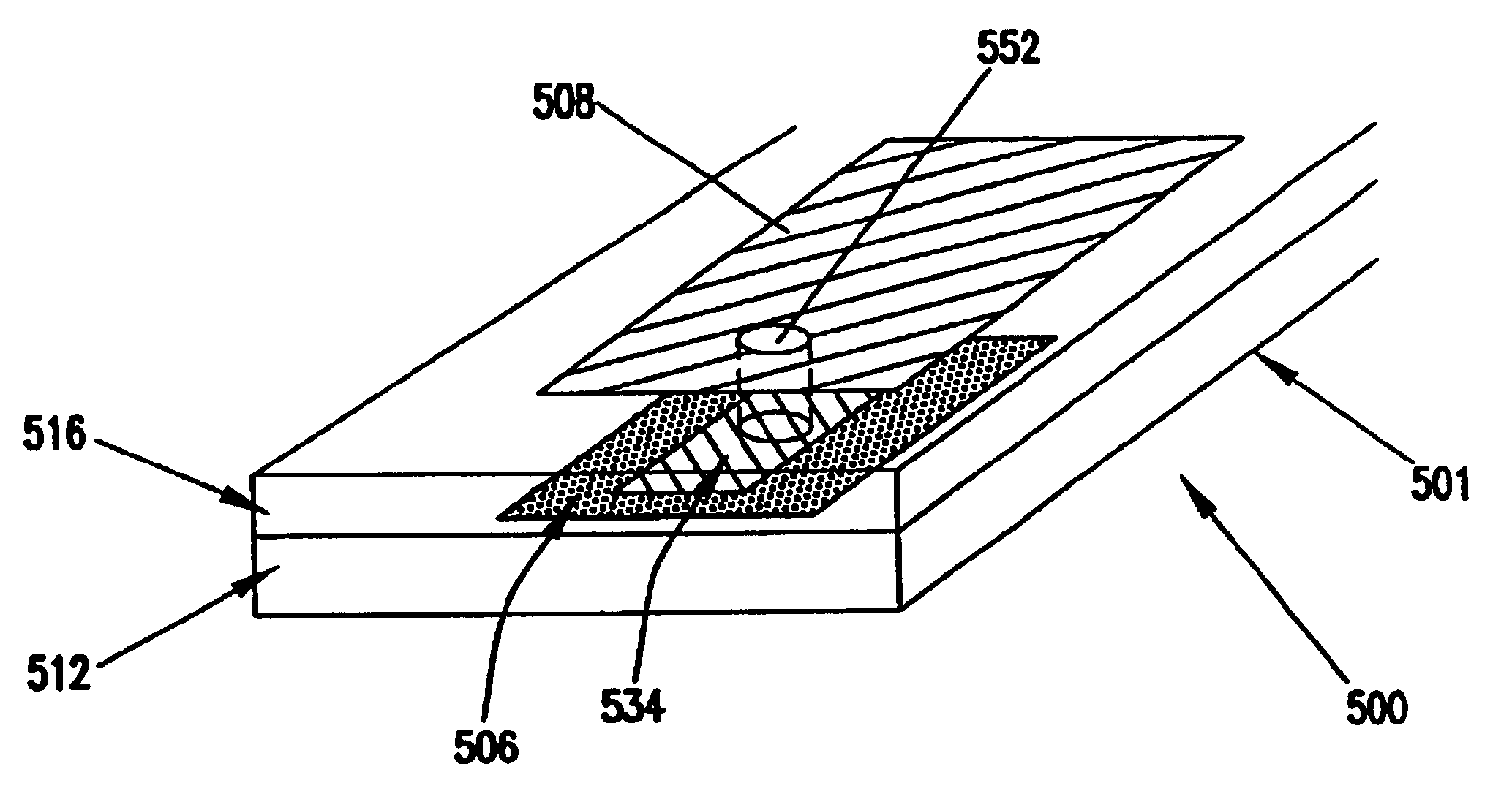
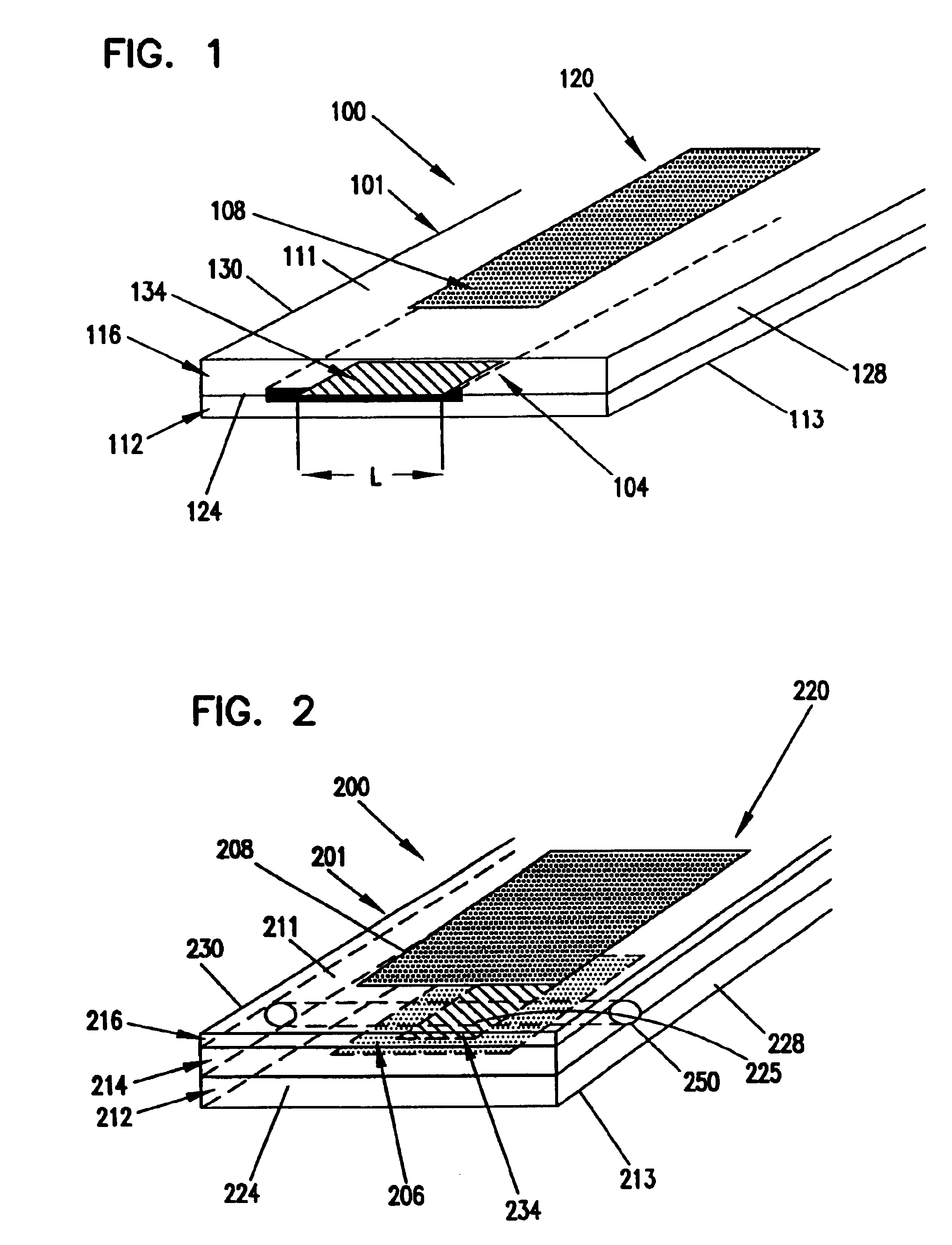
[0080]A glucose sensor with key elements similar to those shown in FIGS. 1 and 2 was designed and constructed. The working electrode and sensing layer were formed in a manner very similar to that shown in FIG. 1, but the working electrode and sensing layer were slightly recessed from the distal tip of the sensor. Glucose diffused from the solution to the distal tip and into the recessed working electrode. The Ag / AgCl counter / reference electrode was located in a sandwiched channel, very similar to the channel shown in FIG. 2.

[0081]The sensor was constructed as follows. A piece of polyester approximately 150 μm thick was printed with Ercon G449 graphite ink (Ercon, Inc., Wareham, Mass.) to a trace width of approximately 750 μm and an ink thickness of about 12 μm. The polyester was cut to a width of approximately 3 mm so that the ink trace was centered. Enzyme / redox polymer sensing chemistry was applied to the distal end of the carbon trace as three 0.1 μL drops, allowing the drops to ...

example 2

[0087]The glucose sensor illustrated in FIG. 1 was prepared by printing graphite ink onto a polyester substrate, applying the sensing chemistry, then coating urethane encapsulant over the dried sensing layer. A separate Ag / AgCl reference electrode was used as the counter electrode.

[0088]A piece of polyester was printed with ERCON G449 graphite ink (ERCON, Inc., Wareham, Mass.) to a trace width of approximately 750 microns and a thickness of 12 microns. The enzyme / redox polymer sensing chemistry was applied as a single 4 nL droplet to the distal end of the sensor and dried at 53° C. for 40 seconds.

[0089]The sensor was placed in an environmental chamber maintained at 80% RH (relative humidity) and 25° C. for 24 hours. A moisture-curable urethane prepolymer was coated at 80% RH and 25° C. over the electrodes and sensing layer using a 2½ wire wound rod. The urethane was cured after 12 hours at the elevated humidity. After cure, the sensing layer was exposed by slitting through the cente...

example 3

[0093]The electrode preparation procedure from Example 2 was repeated to make a sensor for this example, except the sensing layer was composed of 52.3 wt. % X5, 12.3 wt. % glucose oxidase, 35.4 wt. % PEG-400-DGE at 15 wt. % solids in dilute HEPES buffer. 40 nL of the solution was applied to each sensor trace, and then dried at ambient conditions. The urethane was cured at ambient conditions. The results shown in FIG. 10 indicate that the current declined at an average rate equal to 0.35% / hour over the 64 hour stability study. The calibration data collected before and after the stability experiment, shown in FIGS. 11 and 12, indicate a comparable loss of current with good sensitivity extending to high glucose concentrations. The curve marked with the diamonds in FIGS. 11 and 12 represent the data from the sensor in this example.


PUM


Abstract

An in vivo electrochemical sensor including a working electrode, and an analyte-responsive sensing layer proximate the working electrode. The sensing layer is exposed at an edge of the sensor, wherein the sensor signal is limited, at least in part, by mass transport of analyte to the sensing layer. The sensor is configured and arranged for implantation into the body of a mammal for contact with body fluids of the mammal. The analyte diffuses to the sensing element via the edge of the sensor, thereby restricting mass transport of the analyte to the sensing element. This is because the solution-contacting surface area of the sensor edge is much smaller than an open face of the sensing layer.

Description

RELATED APPLICATIONS[0001]This application is a continuation of U.S. patent application Ser. No. 09 / 595,708, filed Jun. 16,2000, now U.S. Pat. No. 6,654,625, which claims priority to provisional patent application No. 60 / 1 94,61 8, entitled “MASS TRANSPORT LIMITED IN VIVO ANALYTE SENSOR”, filed Apr. 5, 2000 and to U.S. Provisional Patent Application Ser. No. 60 / 139,936, entitled “MASS TRANSPORT LIMITED IN VIVO ANALYTE SENSOR”, filed Jun. 18, 1999, both of which are incorporated herein by reference.FIELD OF THE INVENTION[0002]The invention relates to electrochemical analyte sensors, and more particularly to in vivo electrochemical analyte sensors.BACKGROUND OF THE INVENTION[0003]Subcutaneous glucose sensors based on hydrogen peroxide generation and its electrooxidation are known, for example, as described by David Gough in U.S. Pat. Nos. 4,484,987, 4,671,288, 4,890,620, 4,703,756, 4,650,547 and in Diabetes Care, vol. 5, No. 3, May-June 1982, Part 1, pp. 190-198. In these types of sen...

Claims


Application Information

Patent Timeline
IPC IPC(8): G01N33/483A61B5/00A61B5/145A61B5/1468A61B5/1486C12Q1/00G01N27/327G01N27/416G01N27/49G01N33/487
CPCA61B5/1486A61B5/14865C12Q1/002C12Q1/006Y10S977/925
Inventor SAY, JAMES L.SAKSLUND, HENNINGTOMASCO, MICHAEL F.AUDETT, JAY D.CHO, HYUNYAMASAKI, DUANE O.HELLER, ADAM
Owner ABBOTT DIABETES CARE INC
Why Eureka
Try Eureka