Chemical mechanical polishing slurry

a technology of mechanical polishing and slurry, applied in the field of chemical mechanical polishing, can solve the problems of increasing the cost of slurry, the problem of reducing the work efficiency of workers, and the difficulty of achieving the effect of reducing the damage to the working quality

Inactive Publication Date: 2005-12-20
LI FAMILY HLDG
View PDF83 Cites 15 Cited by
  • Summary
  • Abstract
  • Description
  • Claims
  • Application Information

AI Technical Summary

Benefits of technology

[0026]Yet another object of this invention is to minimize damages on the working quality of a planarizing liquid suspension by making the solid abrasive particles practically forever sharp prior to use;

Problems solved by technology

CMP is no longer a niche application with the same fixed equipment, material, and process for all device designs, material and process selections.
In particular, device miniaturization and the coming of multi-metal architectures and techniques such as the emerging copper dual damascene are seriously challenging.
Current CMP is not perfect.
A poorly executed CMP can generate extreme metal dishing in wide structures or dielectric erosion in high-density regions of smaller features.
Abrasive particles containing slurries generate scratches or gouges in the inlaid structures.
The process also reveals and highlights preexisting defects such as seams and voids encapsulated in vias and trenches during earlier copper electroplating processes, or delamination of barrier / seed layers from surrounding dielectrics not easily detected in preceding operations.
Shifts in film microstructure through the thickness of the deposit may affect CMP rates, or lead to effects such as pull-out of grains causing pits in the surfaces or perimeters of the inlaid metal.
CMP technology including equipment, material and processes cannot meet the needs for metal thinning, planarization and defect elimination.
Additional problems exist as to stability and shelf life of the slurry, lot-to-lot variability of slurry products.
Second-step polish often introduces dishing, erosion, and non-uniformity.
In IC manufacturing, CMP involves competing requirements at various length scales—e.g., uniform removal at the wafer scale, but non-uniform removal of protruding surfaces or areas to achieve planarization at the feature scale.
A perfectly planarized sample is often too costly or even impossible to obtain.
A single major defect in any one step can result in the rejection of the entire chip lot.
This is a big production and financial loss.
But these machines are not satisfactory in many respects.
The liquid suspension is costly but is not reproducible; has short shelf lives; deteriorates in performance during use, transit, or even storage; and does not reliably produce quality product results.
The solid abrasive particles wear out rapidly degrading the planarizing results.
Changes in particle size, e.g., over 10 to 20% over the average size, alone, lead to loss of control of the desired surface finish.
A large size distribution of the solid abrasive particles produces a wide variety of surface finishes of differing smoothness and qualities, hampering product yield and reproducibility.
The hard, sharp, and brittle working edges and points on the solid abrasive particles are easily damaged, producing products of variable quality even during the same planarizing run.
Damaged or worn-out particles always give inferior results.
The planarizing process is then inefficient, costly and nonreproducible.

Method used


Image

  • Chemical mechanical polishing slurry
  • Chemical mechanical polishing slurry

Examples


Embodiment Construction

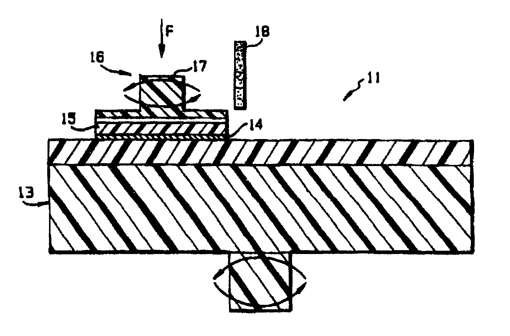
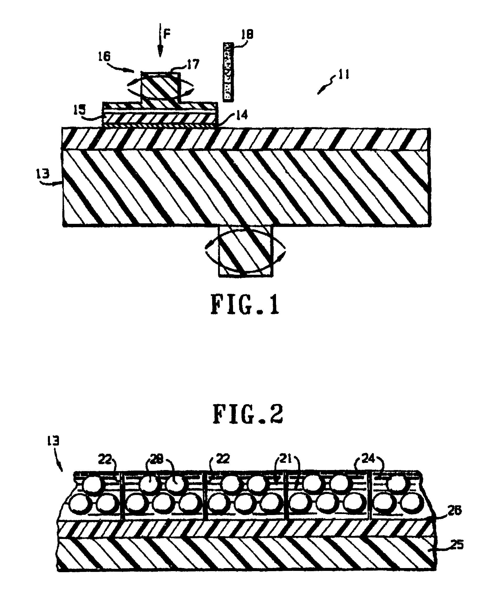
[0037]A principal planarizing problem is the difficulty of maintaining a uniform, high-quality liquid slurry of planarizing suspension. This suspension must be reproducible, not easily damaged and, therefore, longer lasting. A new planarizing suspension is designed to maintain the solid abrasive particles “forever-sharp” during processing, use, transit, or even storage of the liquid abrasive suspensions.

[0038]Each of the very fine, micron or nanometer size range solid abrasive particles (typically of Al2O3 or CeO) has many tiny, rigid, sharp, yet brittle working edges and points on its outer surfaces. The shape, size, perfection, and sharpness of these microscopic planarizing edges and points determine the cost, life, and performance of the planarizing liquid suspension slurry and, in fact, the entire planarizing operation.

[0039]During their useful life, the solid abrasive particles, together with their sharp edges and points, continuously touch, contact, impact, and degrade one ano...


PUM

PropertyMeasurementUnit
densityaaaaaaaaaa
sizesaaaaaaaaaa
pressureaaaaaaaaaa

Abstract

A liquid suspension for planarizing an outer surface of a material comprises a liquid suspension medium of a specific liquid density; and a plurality of solid, contact-sensitive abrasive particles of a constant solid density and suspended in the liquid suspension medium. The liquid and solid densities are approximately the same so that the abrasive particles freely and stably suspend in the liquid suspension medium, without gravitational separation by settling down or floating up. In this way, damaging contacts of the solid abrasive particles with one another are minimized.

Description

REFERENCE TO RELATED APPLICATIONS[0001]This is a continuation-in-part (CIP) of U.S. application Ser. No. 10 / 146,137 filed May 16, 2002 now U.S. Pat. No. 6,676,492, and Ser. No. 09 / 391,596 filed Sep. 8, 1999 now U.S. Pat. No. 6,458,017, now allowed. The '596 application is a CIP of Ser. No. 09 / 112,182 filed Jul. 9, 1998 now abandoned. These applications are all hereby incorporated by reference.BACKGROUND OF THE INVENTION[0002]1. Field. Field[0003]This invention relates to chemical mechanical polishing (CMP), and more particularly to improved chemical mechanical polishing with improved reproducibility, versatility, productivity, robustness, and low cost.[0004]2. Prior Art[0005]CMP is uniquely capable of removing thick metal films while leaving intact features inset and surrounding dielectric films in integrated circuit processing. This process has become an enabling technology for both advanced tungsten plug and copper demanscence processes. It aims to achieve global planarity, and is...

Claims


Application Information

Patent Timeline
Patent Type & Authority Patents(United States)
IPC IPC(8): B24B37/04C09G1/02
CPCB24B37/044C09G1/02
Inventor LI, CHOU H.LI, SUZANNE C.
Owner LI FAMILY HLDG
Why Eureka
Try Eureka