
Manufacturing method of front-end component of endoscope

a technology of endoscope and manufacturing method, which is applied in the direction of manufacturing tools, instruments, lenses, etc., can solve the problems of affecting the adhesion of pollution substances, and affecting the visual field of observation,

Inactive Publication Date: 2005-12-20
FUJI PHOTO OPTICAL CO LTD
View PDF4 Cites 38 Cited by
  • Summary
  • Abstract
  • Description
  • Claims
  • Application Information

AI Technical Summary

Benefits of technology

"The invention provides a method of manufacturing a front-end optical component for an endoscope without using adhesive. The method involves placing a lens raw material on the front-end side of a metallic lens-barrel and press-forming it with a pair of upper and lower shaping dies to tightly join the outer edge of the pressed lens raw material to the inner peripheral surface of the lens-barrel. The coefficient of linear thermal expansion of the metallic material is selected to be equal to or more than the coefficient of linear thermal expansion of the lens raw material to fasten the lens raw material in a cooling process after heat pressurizing. This method prevents the entry of moisture into the lens-barrel and ensures the lens raw material and the front-end side of the lens-barrel can be joined to each other into one piece without using adhesive."

Problems solved by technology

For example, during testing, a pollution substance, such as a body fluid, can adhere to the surface of the first lens exposed to the outside at the front end of the inserting portion, and the adherence of the pollution substance may impair the visual field of observation.
As a result of cooling the first lens, if moisture is contained in the air in the lens-barrel, fogging or condensation can be caused on the inside surface side of the first lens.
Moreover, because the inside surface of the first lens is configured by a concavely curved surface and its curvature is large, the temperature decrease is most remarkable at the central portion thinnest in thickness and its neighborhood in the first lens, thus resulting in fogging or condensation concentrated on the central portion in the concave surface of the first lens.
Since light beams necessary for image formation is concentrated in the central portion of the concave surface of the first lens, least fogging of this region would cause rapid decrease in the image quality of observational images obtained, thereby resulting in a very difficult-to-look image.
Further, in some other cases, when the front end of the inserting portion is also quickly cooled, there is also a fear that fogging or condensation may take place on the first lens and the like.
The adhesive is pervious to water in nature, and therefore moisture enters into the lens-barrel through an adhesive layer between the first lens and the lens-barrel, resulting in fogging of the first lens.

Method used


Image

  • Manufacturing method of front-end component of endoscope
  • Manufacturing method of front-end component of endoscope
  • Manufacturing method of front-end component of endoscope

Examples


Embodiment Construction

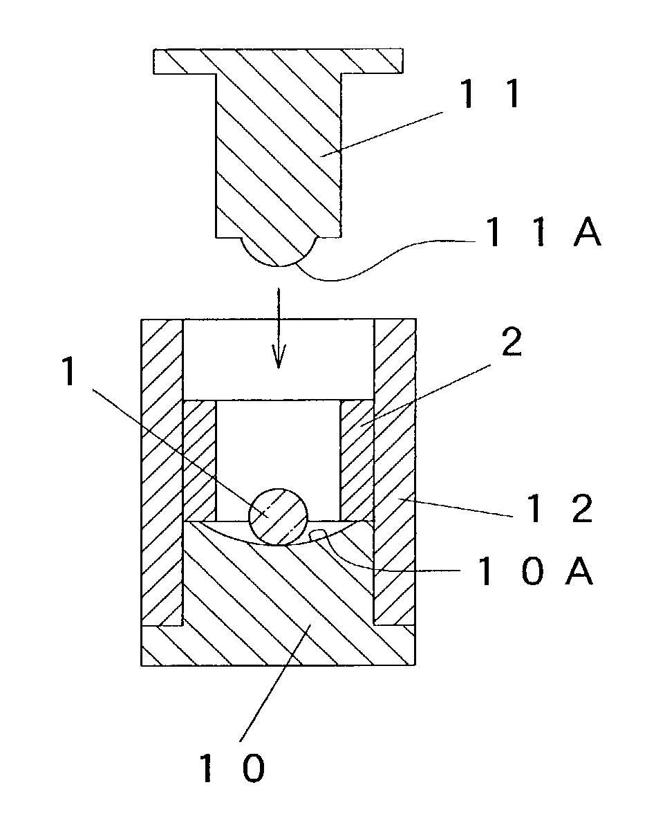
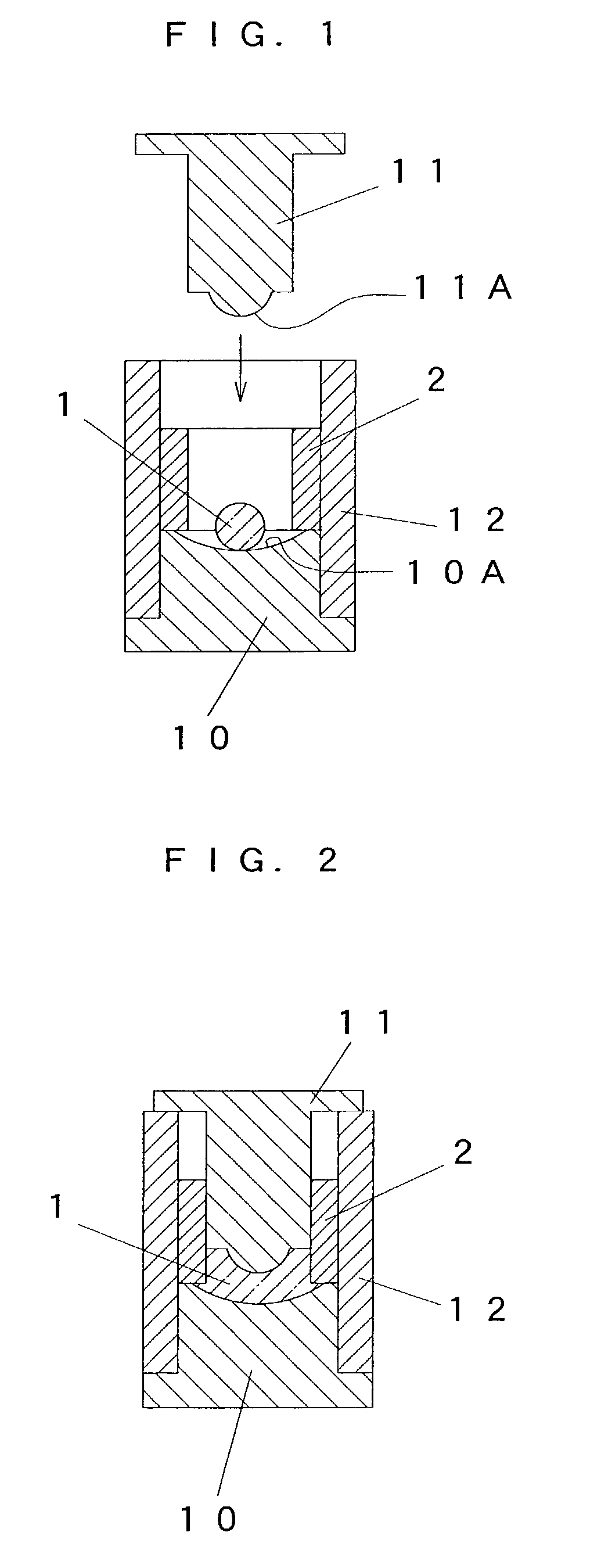
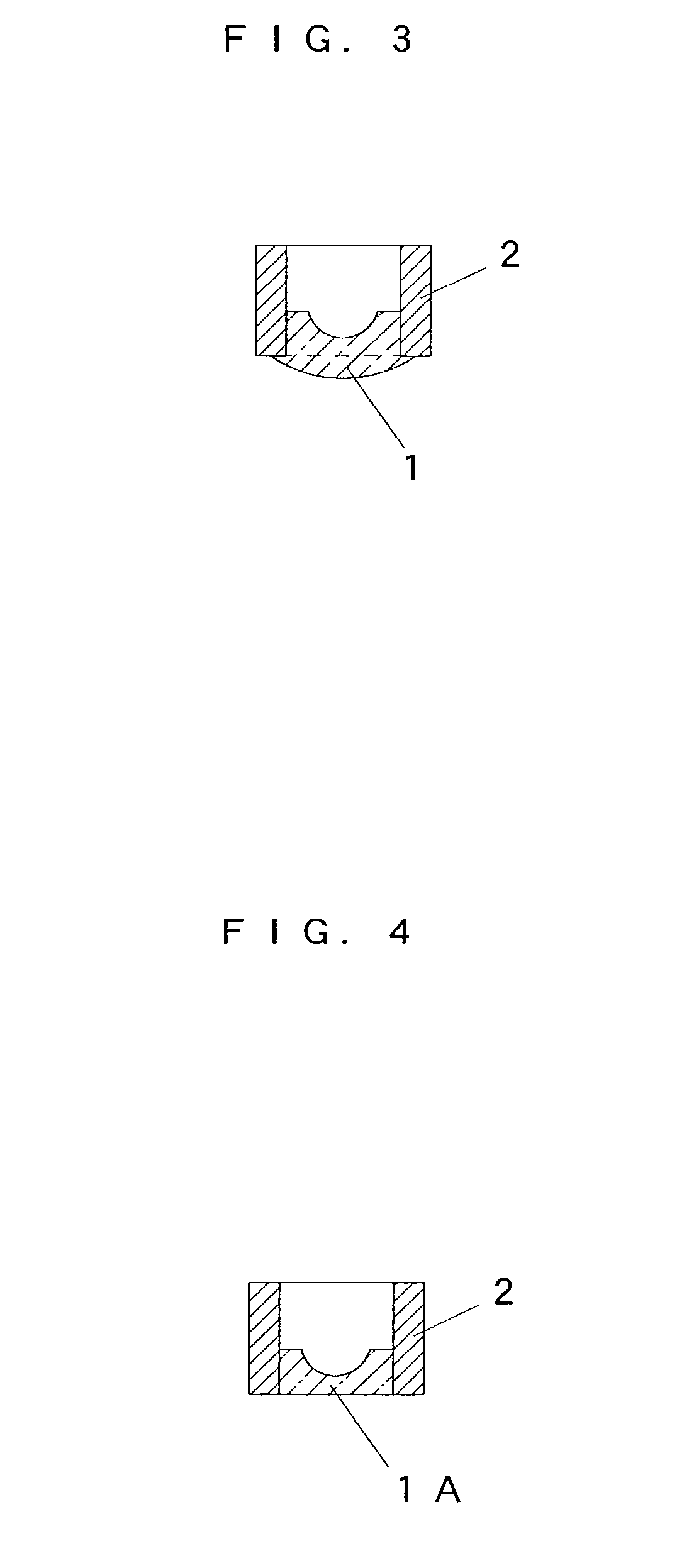
[0018]In FIG. 1, a transfer surface 10A is shape on the top surface of a lower die 10, a transfer surface 11A is shaped on the bottom surface of a upper die 11, and a lens raw material 1 is adapted to be press-formed by a pair of the upper and lower shaping dies 10 and 11. A guide die 12 is mounted on the lower die 10, and the barrel die 12 and the lower die 10 together supports a metallic lens-barrel 2. The upper die 11 is adapted to be inserted into the lens-barrel 2. Further, the lens raw material 1 is placed on the transfer surface 10A of the lower die 10, and positioned on the front-end side of the lens-barrel 2. The front end of the lens-barrel 2 is placed on the lower die 10 to straddle the outer periphery of the transfer surface 10A.

[0019]FIG. 2 is a cross sectional view for showing a state in which the upper die 11 is inserted into the lens-barrel 2 to press the lens raw material 1 in cooperation with the lower die 10. Herein, the outer edge of the pressed lens raw material...


PUM

PropertyMeasurementUnit
coefficient of linear thermal expansionaaaaaaaaaa
coefficients of linear thermal expansionaaaaaaaaaa
temperatureaaaaaaaaaa

Abstract

The invention relates to a method of manufacturing a front-end optical component of an endoscope realizing resistance to humidity. In the method of manufacturing a front-end optical component in which a lens is mounted on the front end of a metallic lens-barrel provided on the front end of the inserting portion of an endoscope, the configuration is made such that a lens raw material is placed on the front-end side in the lens-barrel, the lens raw material is press-formed in a heat-softened state with a pair of upper and lower shaping dies, thereby tightly joining the outer edge of the pressed lens raw material to the inner peripheral surface of the lens-barrel.

Description

BACKGROUND OF THE INVENTION[0001]1. Field of the Invention[0002]The invention relates to a method of manufacturing a front-end optical component in which a lens is mounted on the front end of the lens-barrel provided at the front-end of the inserting portion of an endoscope.[0003]2. Description of the Related Art[0004]Although a front-end optical component configuring the inserting portion of an endoscope has a lens mounted at the front end of the lens-barrel, the lens is bonded and fixed to the inside surface of the lens-barrel with a epoxy-based adhesive. For example, in the front-end optical components of the endoscopes disclosed in the gazettes of Japanese Patent Laid-Open No. 10-234652 and Japanese Patent Laid-Open No. 10-170794, both of the lens are fixed to the lens-barrels with adhesives.[0005]The main body of the front-end portion in the inserting portion of an endoscope is provided with observing means having an objective optical system positioned in the proximity of illum...

Claims


Application Information

Patent Timeline
Patent Type & Authority Patents(United States)
IPC IPC(8): C03C27/02G02B23/26G02B3/00G02B7/02
CPCA61B1/00096A61B1/00101C03C27/02
Inventor MUKASA, KATSUNORIFUJITA, HIROAKI
Owner FUJI PHOTO OPTICAL CO LTD
Learn More