
Textile heating device

a heating device and a technology of a textile, applied in the direction of fluid heaters, heating types, lighting and heating apparatus, etc., can solve the problems of often inadequate requirements, achieve effective and economical contact of heating strands, reduce the distance to be electrically bridged between two electrode strands, and reduce the resistance

Inactive Publication Date: 2005-12-20
GENTHERM GMBH
View PDF10 Cites 63 Cited by
  • Summary
  • Abstract
  • Description
  • Claims
  • Application Information

AI Technical Summary

Benefits of technology

[0010]In another advantageous embodiment of the invention, additional fixing means are provided to fix the points of contact. Such fixing means comprise means for lasting connection of strands or filaments, such as clips, clamps or adhesives. The filaments / strands, however, may alternatively be connected by welding or compressing at their points of contact. Depending on the kind of textile employed, viz. woven, knit or other stuff, or on the materials employed, the modes of fixation just enumerated by way of example afford advantages respecting production costs or outlay, load capacity, i.e. desired service life, and material properties of the heating textile, for example elasticity and deformability.
[0012]In a preferred refinement of the invention, electrode strands or filaments are knitted into the heating textile. These electrode strands possess a definitely lower resistance than the heating strands and serve to contact them. Specifically, the electrode strands are worked in at least at opposed ends of the heating textile and thus advantageously permit an effective and economical contacting of the heating strands.
[0013]In another preferred refinement of the invention, at least a portion of the plurality of electrode strands are arranged distanced from each other and running essentially in the same direction of extension. Advantageously, what this accomplishes is that the distance between the electrode strands, i.e. the distance to be electrically bridged between two electrode strands, is reduced. Compared to the great distance when the electrode filaments are provided only at opposed ends of the heating textile, this distance is subdivided into a plurality of smaller distances. Therefore, the resistance present between two neighboring electrode strands is reduced correspondingly. A heating device according to the invention, having electrode strands worked in, may consequently be advantageously operated at lower voltage. With unchanged voltage, on the other hand, heating strands of higher ohmage may be employed.
[0015]In an advantageous refinement, the points of contact of electrode strands and heating strands are of fixed design. Here, the same fixations are used as are also employed to fix the points of contact of the heating strands among themselves. In conventional contactings, electrode strands are sewn onto a heating textile, arranged side-by-side, usually in 5- or 7-fold redundancy, to ensure a secure contact with the heating conductors. This advantageous refinement permits a reduction of the number of electrode strands to one or two strands in each instance, since the electrical contacts between heating strand and electrode strand is brought about, securely and reliably, by fixation of the connection, or point of contact, for example by knotting or by means of auxiliary filaments.

Problems solved by technology

In practice, however, it turns out that this requirement is often inadequately met.

Method used


Image

  • Textile heating device
  • Textile heating device
  • Textile heating device

Examples


Embodiment Construction

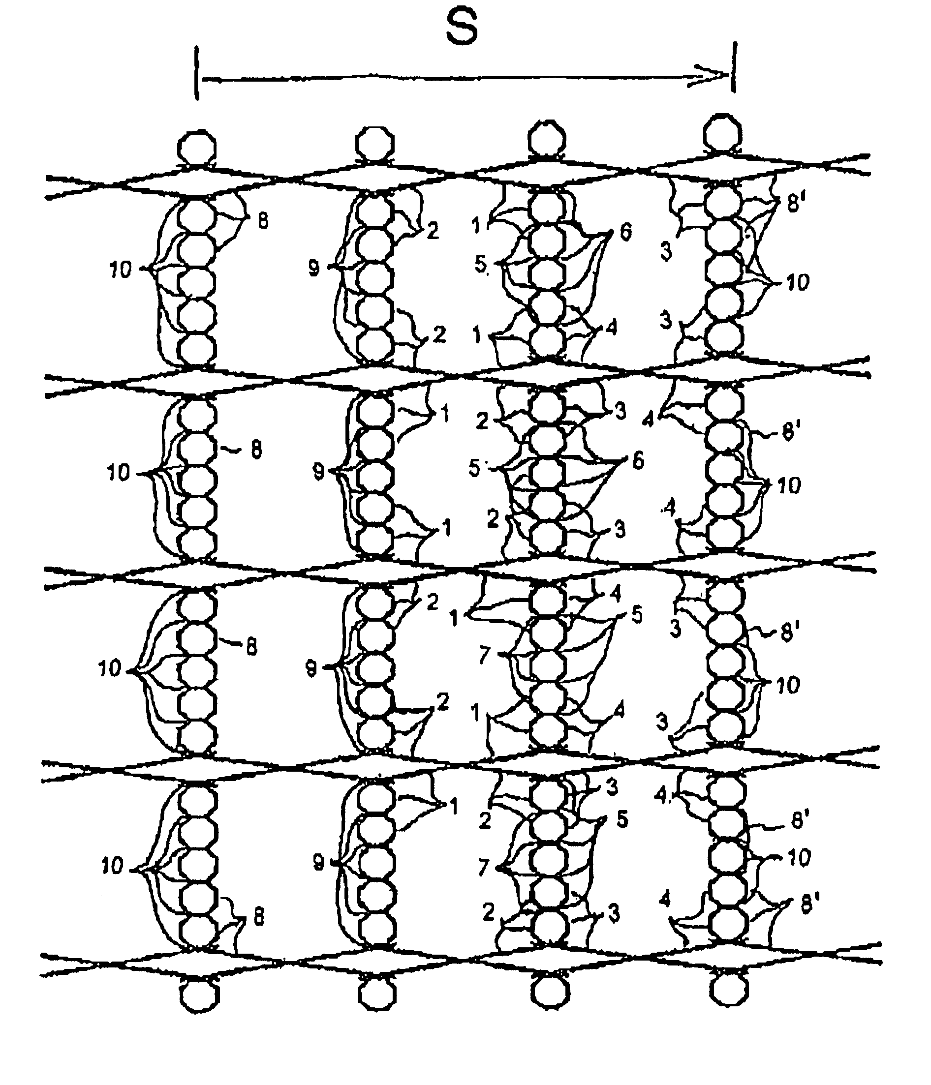
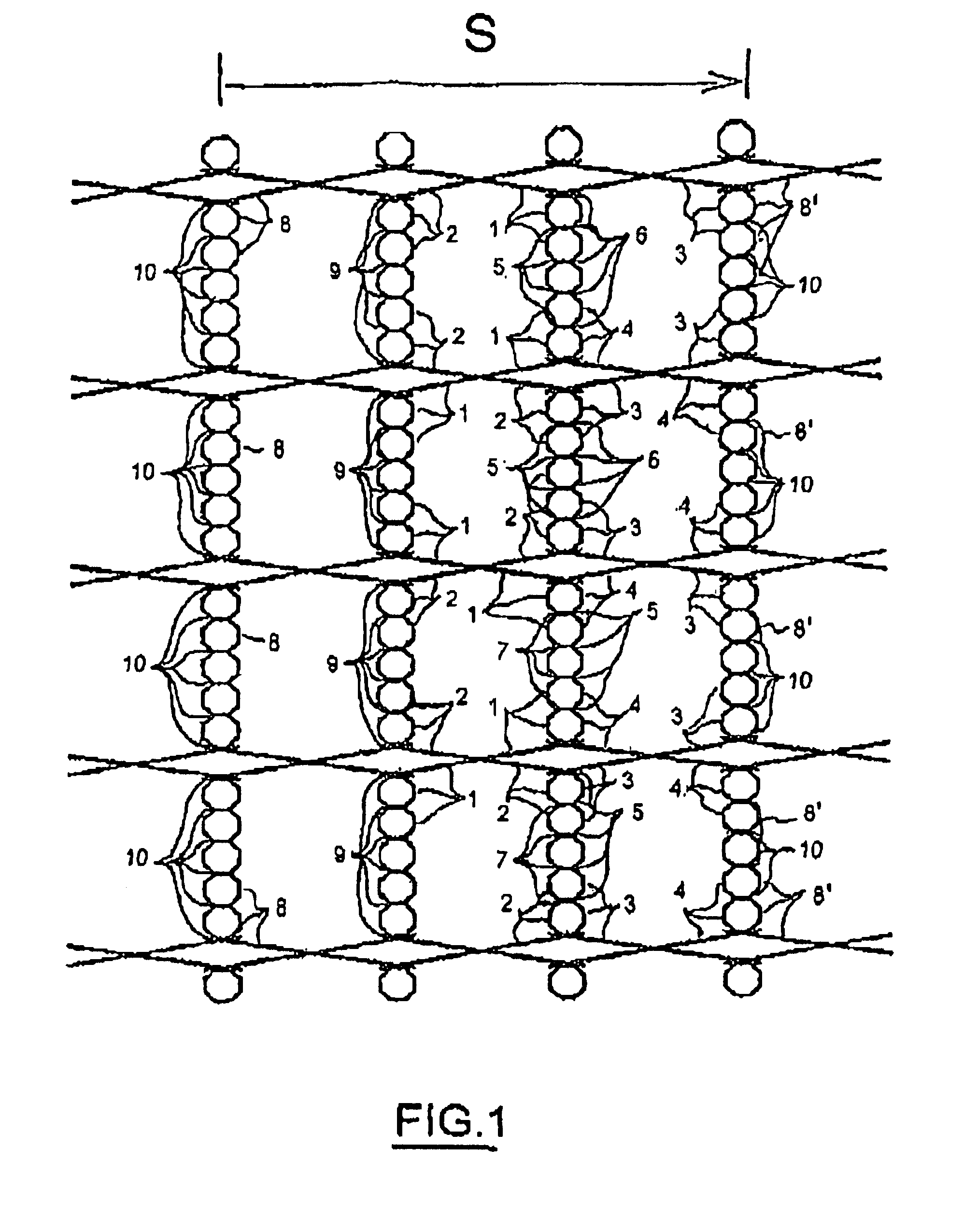
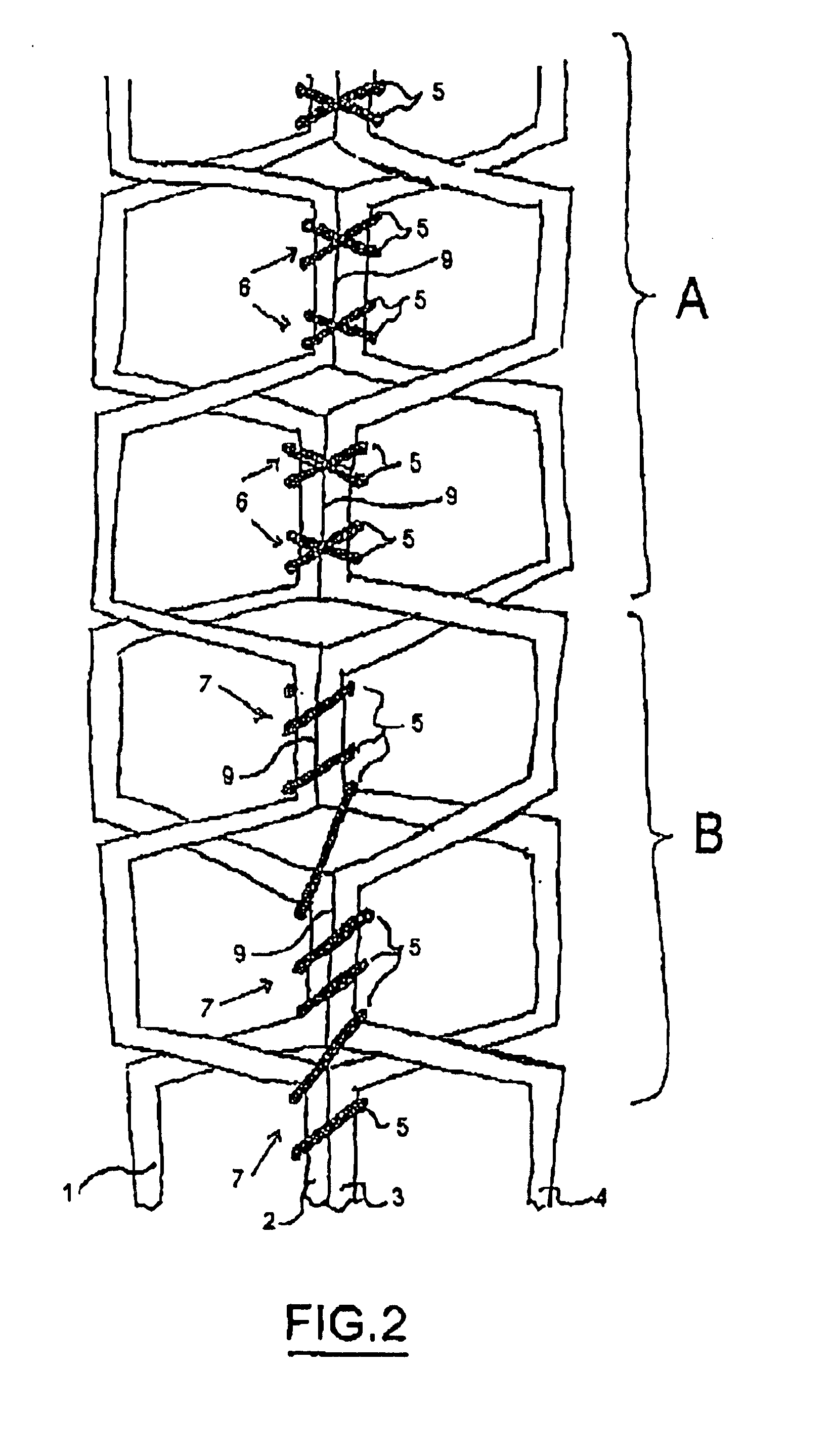
[0022]FIG. 1 shows, in enlarged representation, a portion of a heating textile according to the invention, present in the form of a knit fabric. The knit consists basically of three different types of strands or filaments. Reference numerals 1 to 4 and 8 and 8′ designate strands serving as conductors of electric current. Specifically, they are heating strands 1 to 4 and electrode strands 8, 8′ of the knit. On the other hand, reference numeral 5 designates a connecting filament, making a fixed connection of the points of contact 9, 10 of the electrically conductive strands 1 to 4, 8, 8′. The arrow designated by the letter S indicates the direction of the flow of current through the heating textile when a correspondingly directed voltage is applied to the electrode strands 8, 8′.

[0023]For the electrical junction of a heating textile, use is made of electrodes, commonly bonded, sewn, riveted or otherwise attached to the textile conductively by means familiar to those skilled in the art...


PUM


Abstract

A textile heating device having a plurality of electrically conductive heating strands in contact with each other at a plurality of points of contact by way of respective contact surfaces is provided. The electrically conductive textile includes at least two strands which are fixed relative to each other at at least one point of contact such that a contact area at the fixed at least one point of contact between the contact surfaces remains essentially constant during mechanical action of the textile.

Description

BACKGROUND OF THE INVENTION[0001]The present invention relates to a textile heating device.[0002]Textile heating devices are known in principle. They are based on electrically conductive textiles, or electrically conductive textile filaments, used as electrical resistance conductors for heating. The conductivity of the textile, or of the filament, is brought about for example by metallic coating of the fibers or by inclusion of graphite particles in synthetic filaments. As textiles for the generic heating devices, woven and knit fabrics are employed in particular.[0003]A temperature control is usually effected in terms of controlling the voltage and / or current of the textile heating device. Hence, an accurate and dependable temperature control requires as accurate a knowledge as possible of the electrical resistance of the textile, or of the textile heating device. In practice, however, it turns out that this requirement is often inadequately met. The resistances of the heating devi...

Claims


Application Information

Patent Timeline
IPC IPC(8): H05B3/14H05B3/20H05B3/34
CPCH05B3/345H05B2203/014H05B2203/017H05B2203/029
Inventor WEISS, MICHAEL
Owner GENTHERM GMBH
Features
  • Generate Ideas
  • Intellectual Property
  • Life Sciences
  • Materials
  • Tech Scout
  • Unparalleled Data Quality
  • Higher Quality Content
  • 60% Fewer Hallucinations
Learn More