Configurable matrix receiver for MRI

a matrix receiver and receiver technology, applied in the field of apparatus and methods for detecting and analyzing signals, can solve the problems of quantization noise, quantization noise, and difficulty in detecting the quantization value of the signal,

Active Publication Date: 2005-12-20
FONAR
View PDF37 Cites 193 Cited by
  • Summary
  • Abstract
  • Description
  • Claims
  • Application Information

AI Technical Summary

Benefits of technology

[0017]In another embodiment of the invention, a signal processing system comprises a one or more antennas for detecting a signal, and a configurable matrix receiver. The configurable matrix receiver comprises a plurality of amplifiers for applying various gains to the signal, one or more switches for connecting the amplifiers in series fashion, one or more analog-to-digital converters (ADCs) for converting the output signals

Problems solved by technology

In an MRI system, the need to process signals having widely varying ranges poses particular challenges.
One such difficulty is related to the problem of quantization noise.
Quantization noise is a type of noise that results from error in the conversion of an analog signal to a digital form by an ADC.
When a smooth analog signal is transformed into a signal with steps, a certain amount of error results because portions of the analog signal between the steps must be converted to a signal that skips from one step to another rather than smoothly varying between them.
However, there are practical reasons for using the ADC with the smallest number of steps possible.
One is that using more steps can make the downstream equipment that uses the digital signal very expensive because each signal level must be encoded by a large amount of data.
The design of signal conditioning systems involving the conversion of analog signals to digital form invariably confronts the issue of quantization noise, although in most cases, it is just a routine step in the design process.
But in some kinds of signal analysis systems, including MRI systems, quantization noise is not so easily addressed.
In MRI systems, this problem is acute because useful

Method used


Image

  • Configurable matrix receiver for MRI
  • Configurable matrix receiver for MRI
  • Configurable matrix receiver for MRI

Examples


Embodiment Construction

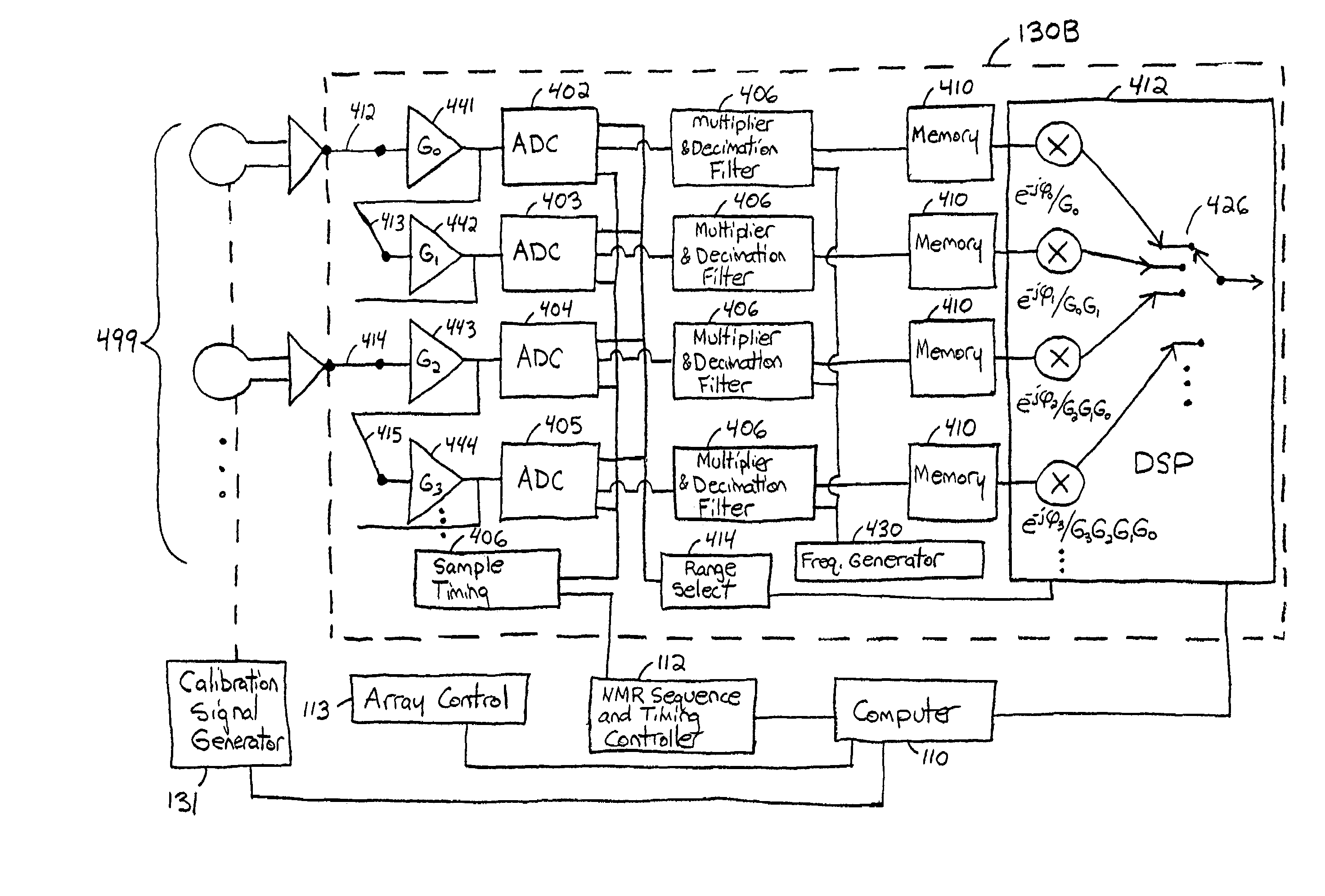
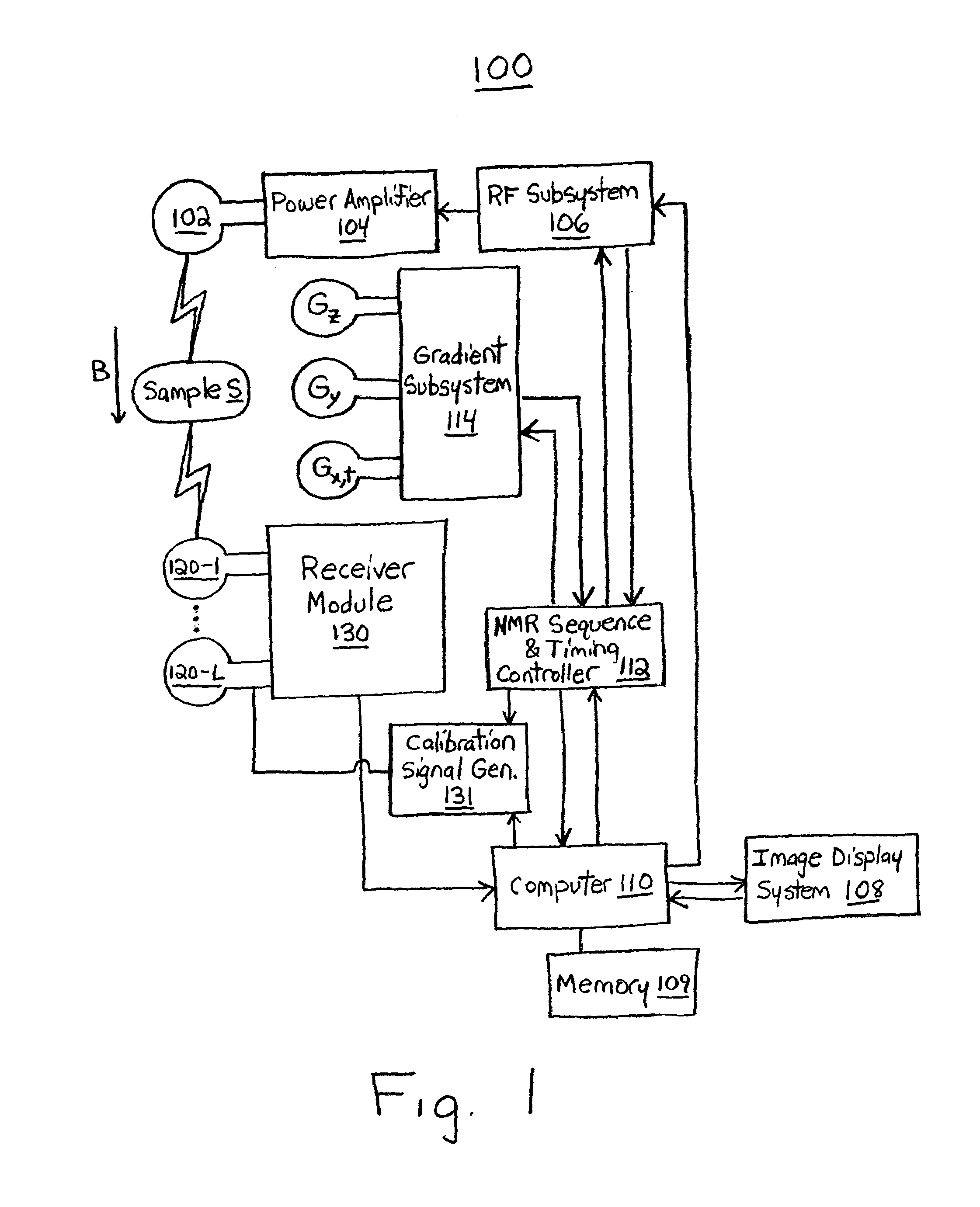
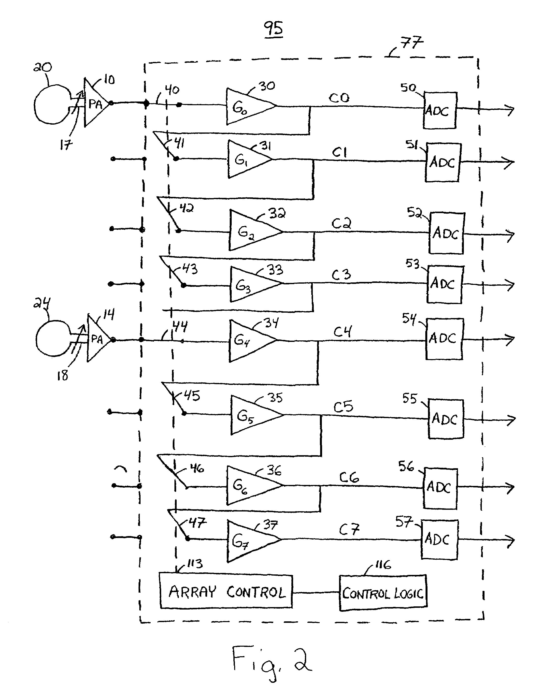
[0031]The present application provides a selectively configurable matrix receiver that can be optimized for different coil arrays. The receiver coil is split into multiple coils that are sensitive to only part of the imaging volume. Each coil is coupled to a different pre-amplifier, amplifier and digitizing channel. The individual coils of the array may be optimized for the particular imaging sub-volume. In one embodiment, the configurable matrix receiver described herein may be utilized, e.g., in an MRI system to perform full body scans.

[0032]In one embodiment, signals are received from an imaging volume by a plurality of receiving coils, e.g., an array. Each coil is coupled to a matrix that includes a plurality of amplifiers and a plurality of digitizers. Because multiple coils are used, each coil is associated with a sub-volume smaller than the entire imaging volume. Since the dynamic range requirement of a coil decreases in proportion to a decrease in the size of the imaging vol...


PUM


Abstract

A configurable matrix receiver comprises a plurality of antennas that detect one or more signals. The antennas are coupled to a configurable matrix comprising a plurality of amplifiers, one or more switches that selectively couple the amplifiers in series fashion, and one or more analog-to-digital converters (ADCs) that convert the output signals generated by the amplifiers to digital form. For example, in one embodiment, a matrix comprises a first amplifier having a first input and a first output, and a second amplifier having a second input and a second output, a switch to couple the first output of the first amplifier to a the second input of the second amplifier, a first ADC coupled to the first output of the first amplifier, and a second ADC coupled to the second output of the second amplifier. In one embodiment, the signals detected by the antennas include magnetic resonance (MR) signals.

Description

[0001]The present application claims priority to Provisional Patent Application No. 60 / 423,596, filed on Nov. 4, 2002, which is assigned to the assignee of the present invention and incorporated by reference herein.FIELD OF THE INVENTION[0002]The present invention is directed to an apparatus and method for detecting and analyzing signals characterized by wide dynamic range, and particularly to such apparatus and methods where the signals are provided by a plurality of antennas that are low in cost and require minimal calibration.BACKGROUND OF THE INVENTION[0003]In a Magnetic Resonance Imaging (MRI) system, a receiving coil detects magnetic resonance properties of a sample of material under study (e.g., a patient's body). The receiving coil outputs a resonance signal that varies greatly in amplitude in very short bursts. To obtain this signal, the sample has to be subjected to various cycles of magnetic fields and a burst of radio energy, after which, the receiving coil receives a bu...

Claims


Application Information

Patent Timeline
IPC IPC(8): G01R33/36G01V3/00
CPCG01R33/3621
Inventor HERTZ, DAVID
Owner FONAR
Why Eureka
Try Eureka