Pulse shaper circuit for sense amplifier enable driver

Active Publication Date: 2005-12-20
ORACLE INT CORP
View PDF10 Cites 4 Cited by
  • Summary
  • Abstract
  • Description
  • Claims
  • Application Information

AI Technical Summary

Benefits of technology

[0008]A sense amplifier pulse shaping circuit maintains a relationship between a sense amplifier enable signal and a sense amplifier equalization enable signal while disabling equalization prior to evaluation and disabling evaluation prior to equalization. In some embodiments of the present invention, a sense amplifier pulse shaper circuit generates a sense amplifier equalization control signal and a sense amplifier enable signal. The sense amplifier equalization control signal has a rising transition effectively earlier than the rising transition of the sense amplifier enable signal. The sense amplifier enable signal has a falling transition effectively earlier than the falling transition of the sense amplifier equalization control signal. The sense amplifier equalization signal is discharged into the sense amplifier enable signal.
[0009]In some embodiments of the present invention, an integrated circuit includes an input node, a first switch coupled to the input node, a second switch coupled to the input node, an impedance coupled to the first and the second switches, a sense amplifier equalization enable node, and a sense amplifier evaluation e

Problems solved by technology

Generally, if the equalization period defined by SE transitions is too short, then the bit-lines may not develop sufficient differential for the sense amplifier to correctly sense the data being read from an addressed memory cell.
However, if two separate drivers are used, a fixed relationship between the signals becomes difficult to maintain due to circuit matching discrepancies, e.g., device mismatches produced by process variations.

Method used


Image

  • Pulse shaper circuit for sense amplifier enable driver
  • Pulse shaper circuit for sense amplifier enable driver
  • Pulse shaper circuit for sense amplifier enable driver

Examples


Embodiment Construction

)

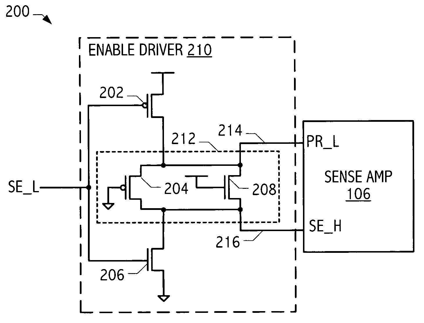
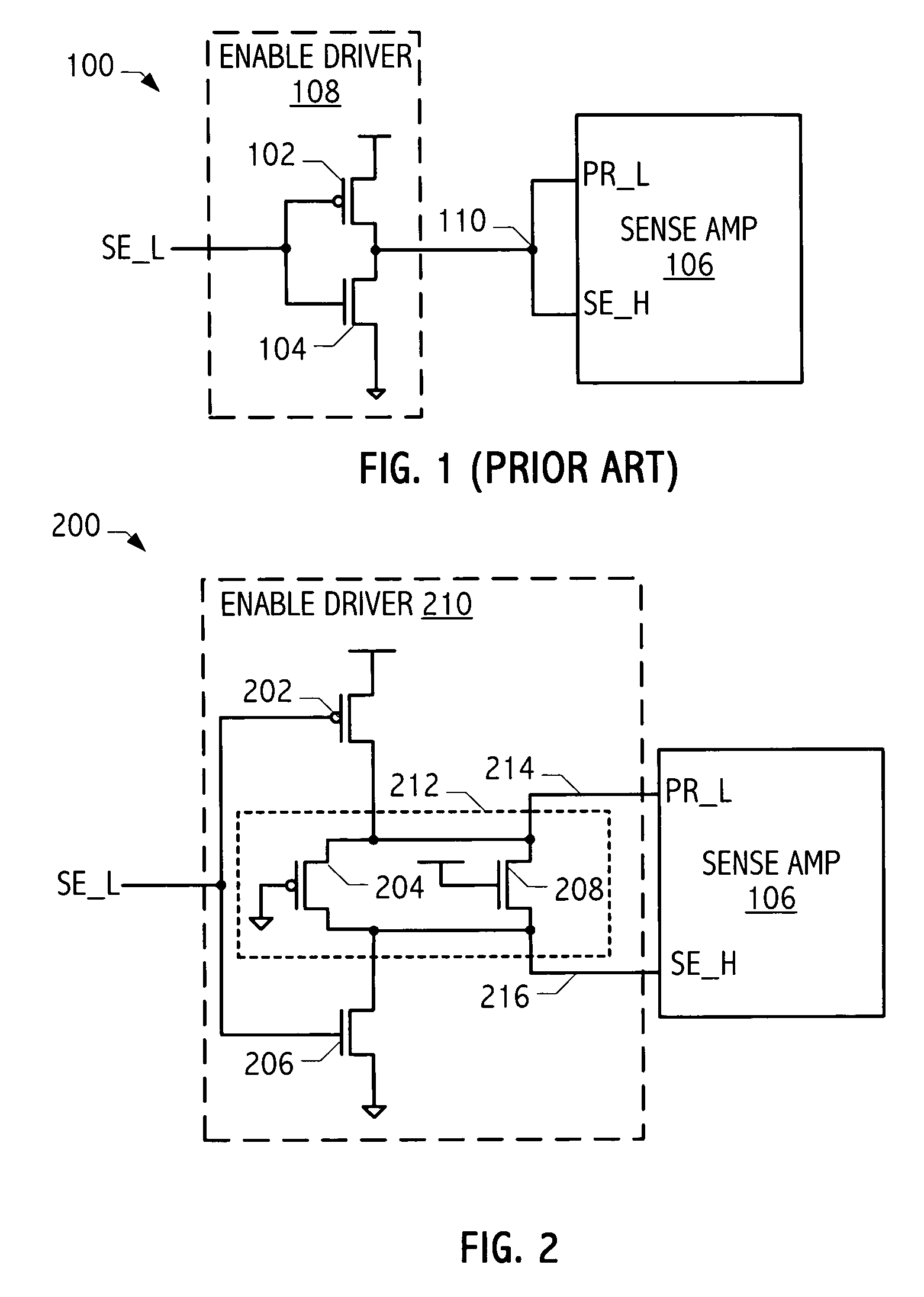
[0016]The description herein focuses on a sense amplifier enable driver that generates a sense amplifier enable signal and a sense amplifier equalization enable signal having different timing requirements but matches characteristics of the two signal paths. Referring to FIG. 1, circuit 100 illustrates an exemplary sense amplifier and enable driver. Sense amplifier 106 is coupled to enable driver circuit 108, which includes p-type transistor 102 and n-type transistor 104. Input SE—L enables both an equalization operation and an evaluation (i.e., sensing) operation of sense amplifier 106. Node 110 drives both PR—L and SE—H. In circuit 100, signal PR—L is an active-low signal for precharging sense amplifier 106 and SE—H is an active-high signal for enabling the evaluation operation of sense amplifier 106. However, in other sense amplifier and enable driver designs, the equalization operation may discharge certain nodes, rather than precharge certain nodes, the equalization operation e...


PUM


Abstract

A sense amplifier pulse shaping circuit maintains a relationship between a sense amplifier enable signal and a sense amplifier equalization enable signal while disabling equalization prior to evaluation and disabling evaluation prior to equalization. In some embodiments of the present invention, a sense amplifier pulse shaper circuit generates a sense amplifier equalization control signal and a sense amplifier enable signal. The sense amplifier equalization control signal has a rising transition effectively earlier than the rising transition of the sense amplifier enable signal. The sense amplifier enable signal has a falling transition effectively earlier than the falling transition of the sense amplifier equalization control signal. The sense amplifier equalization signal is discharged into the sense amplifier enable signal.

Description

BACKGROUND[0001]1. Field of the Invention[0002]The present invention relates generally to integrated circuits and, more particularly, to sense amplifier enable drivers.[0003]2. Description of the Related Art[0004]Typically, modern semiconductor memories (whether embodied in a memory integrated circuit or incorporated in larger designs, e.g., as cache memory of a processor integrated circuit) employ differential bit lines and some sort of differential amplifier or sensing circuit in their design. Such differential amplifier and sensing circuits are commonly known as sense amplifiers (sense amps) and a wide variety of sense amplifier designs are known in the art, including current sensing and voltage sensing variations.[0005]Generally, when designing sense amplifiers, great care is taken to optimize timing and balance. Typically, a signal such as a sense amplifier enable (SE) is used to time sense amplifier operation. For example, one state of an SE signal is often used to equalize se...

Claims


Application Information

Patent Timeline
IPC IPC(8): G01R19/00G11C7/06H03K5/00H03K5/15
CPCG11C7/06H03K5/15G11C2207/065H03K2005/00195
Inventor WANG, PINGKRISHNAMURTHY, MAHESH
Owner ORACLE INT CORP
Why Eureka
Try Eureka