Control circuit for controlling output current at the primary side of a power converter

a power converter and control circuit technology, applied in the field of power converters, can solve problems such as the difficulty of controlling the output current of the power converter

Active Publication Date: 2005-12-20
SEMICON COMPONENTS IND LLC
View PDF4 Cites 258 Cited by
  • Summary
  • Abstract
  • Description
  • Claims
  • Application Information

AI Technical Summary

Problems solved by technology

In case that the control circuit is configured at the primary side of the power converter, it would be difficult to control an output current of the power converter.

Method used


Image

  • Control circuit for controlling output current at the primary side of a power converter
  • Control circuit for controlling output current at the primary side of a power converter
  • Control circuit for controlling output current at the primary side of a power converter

Examples


Embodiment Construction

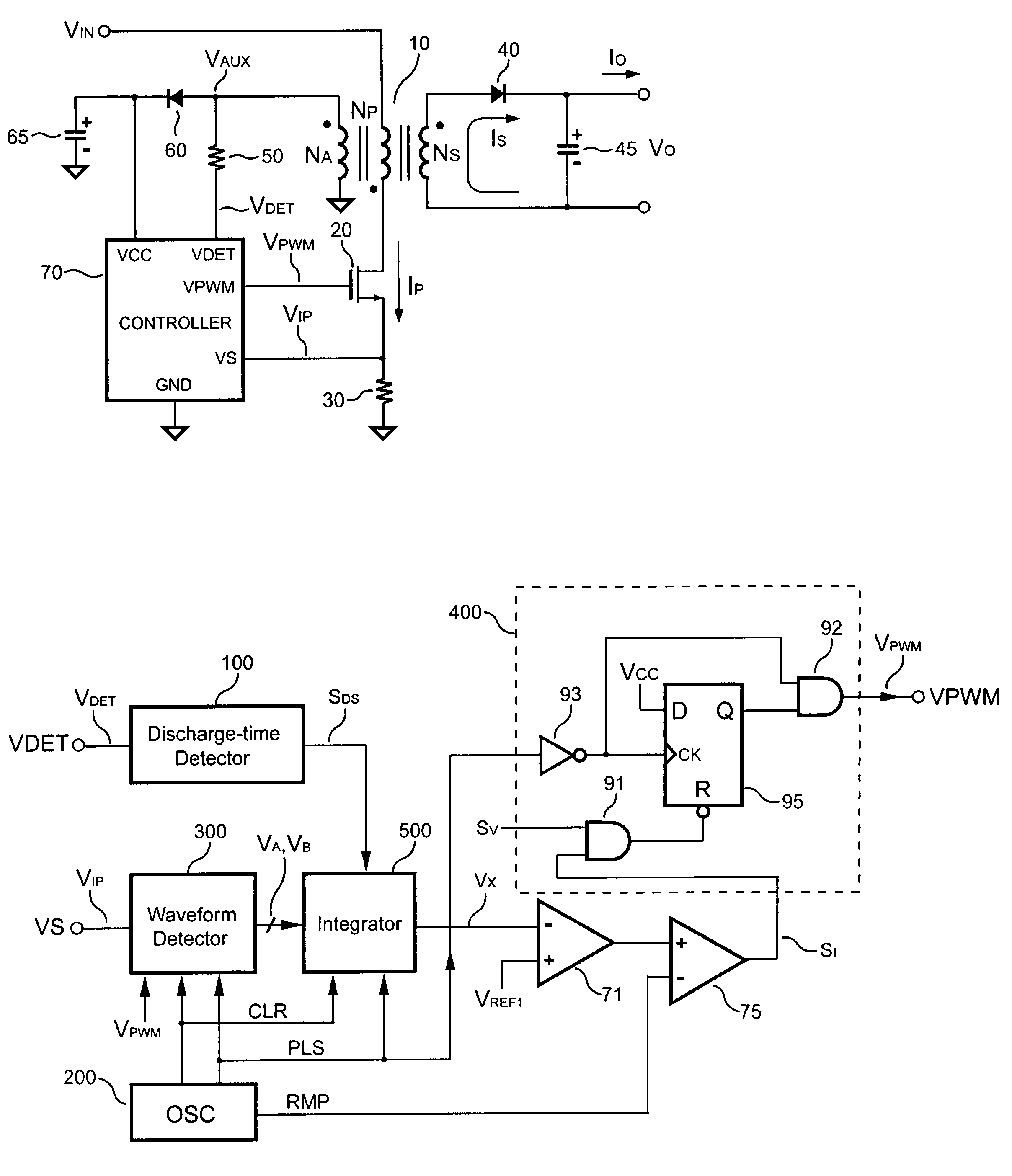
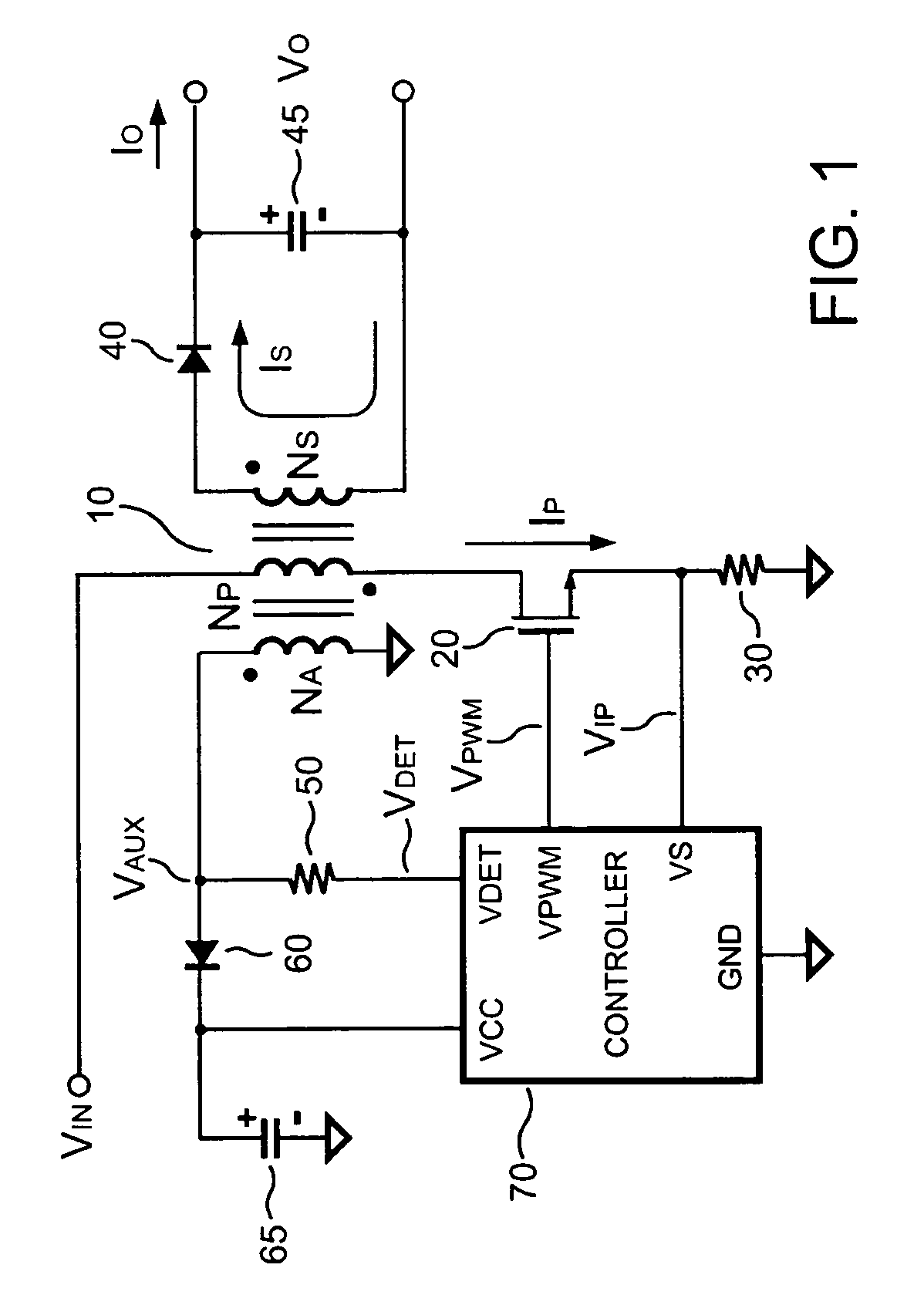
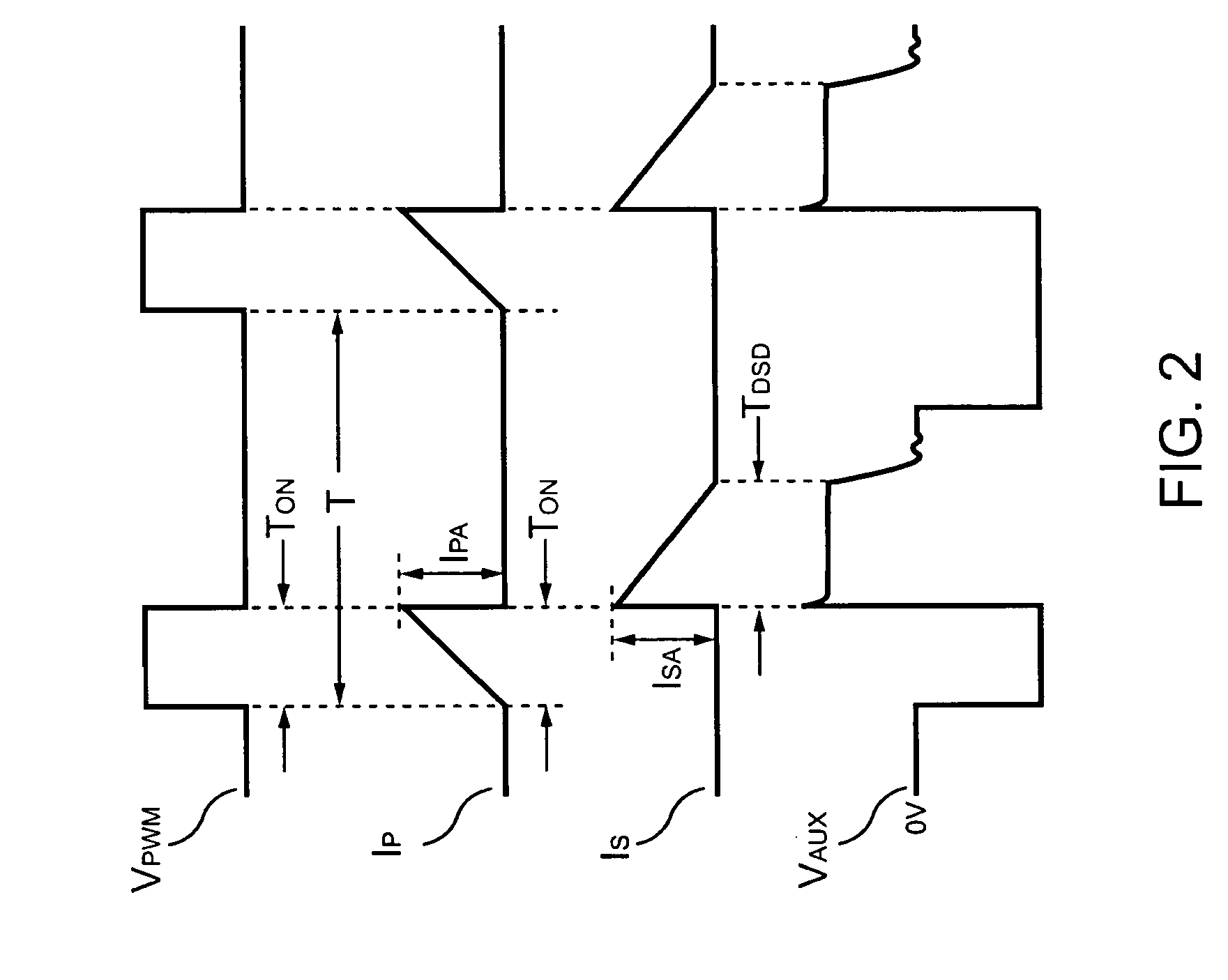
[0017]Referring to FIG. 1, a power converter according to one embodiment of the present invention is illustrated. The power converter comprises a transformer 10 having an auxiliary winding NA, a primary winding NP, and a secondary winding NS. In order to regulate the output voltage VO and / or the output current IO of the power converter, a control circuit 70 generates a switching signal VPWM to switch the transformer 10 by switching a transistor 20. Referring to FIG. 2, it illustrates various signal waveforms of the power converter in FIG. 1 operating in discontinuous conduction mode. A primary side switching current IP is generated as the switching signal VPWM becomes high. A peak value IPA of the primary side switching current IP is given by, IPA=VINLP×TON(1)

where VIN is an input voltage applied to the transformer 10, LP is the inductance of the primary winding NP of the transformer 10, TON is an on-time of the switching signal VPWM.

[0018]Once the switching signal VPWM drops to low...


PUM


Abstract

A control circuit controlling output current at the primary side of a power converter is provided. A waveform detector generates a current-waveform signal. A discharge-time detector detects a discharge-time of a secondary side switching current. An oscillator generates an oscillation signal for determining the switching frequency of the switching signal. An integrator generates an integrated signal by integrating an average current signal with the discharge-time. The average current signal is generated in response to the current-waveform signal. The time constant of the integrator is correlated with the switching period of the switching signal, therefore the integrated signal is proportional to the output current. An error amplifier amplifies the integrated signal and provides a loop gain for output current control. A comparator controls the pulse width of the switching signal in reference to the output of the error amplifier. Therefore, the output current of the power converter can be regulated.

Description

BACKGROUND OF THE INVENTION[0001]1. Field of the Invention[0002]The present invention relates to a power converter, and more particularly, to the control circuit of the power converter.[0003]2. Description of Related Art[0004]Various power converters have been widely used to provide regulated voltage and current. For safety reasons, galvanic isolation is provided between a primary side and a secondary side of an off-line power converter. In case that the control circuit is configured at the primary side of the power converter, it would be difficult to control an output current of the power converter. Thus it is desirable to provide a control circuit for controlling the output current of the power converter at the primary side of the power converter.SUMMARY OF THE INVENTION[0005]The present invention provides a control circuit for controlling an output current at a primary side of a power converter. The control circuit comprises a switching control circuit for generating a switching ...

Claims


Application Information

Patent Timeline
Patent Type & Authority Patents(United States)
IPC IPC(8): H02M3/335
CPCH02M3/33507
Inventor YANG, TA-YUNGHUNG, GUO-KIANG
Owner SEMICON COMPONENTS IND LLC
Why Eureka
Try Eureka