
System for portable sensing

a portable sensing and sensor technology, applied in the field of detection and transmission of sensory data, can solve the problems of not being able to perform data, not being able to predict an impending disaster, not being able to provide results for hours, days or even weeks, etc., to achieve easy implementation, expand the repository of knowledge, and be convenient to share.

Inactive Publication Date: 2005-12-20
SMITHS DETECTION
View PDF41 Cites 64 Cited by
  • Summary
  • Abstract
  • Description
  • Claims
  • Application Information

AI Technical Summary

Benefits of technology

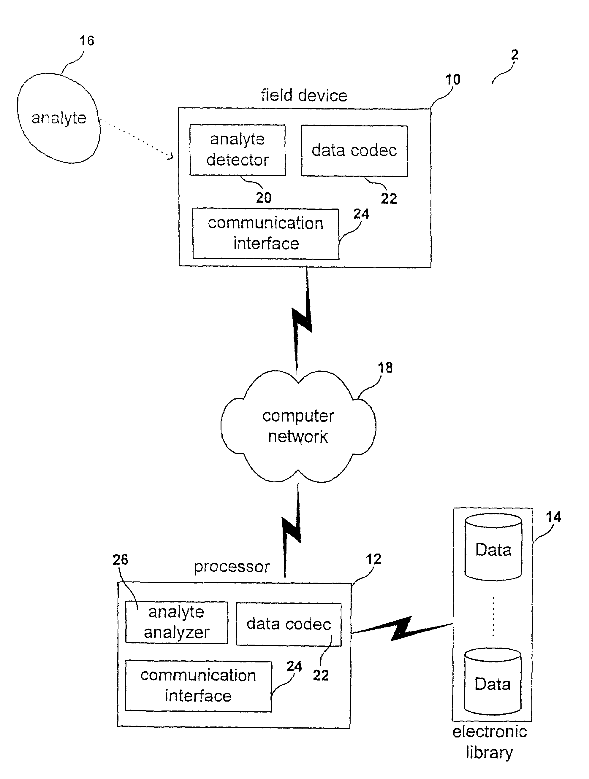
[0011]By transmitting the captured analyte data via a computer network, the present invention provides a system that is capable of transmitting analyte data in a timely and efficient manner. Consequently, analyses can be performed swiftly and results can be obtained on a more expedited basis.
[0012]Numerous benefits are achieved by way of the present invention over conventional techniques. For example, the present invention allows for the efficient transfer of analyte data from one geographic location to another geographic location thereby providing utility and applications in various areas such as hospital / medical applications, fire safety monitoring, environmental toxicology, remediation, biomedicine, material quality control, food monitoring, agricultural monitoring, heavy industrial manufacturing, ambient air monitoring, worker protection, emissions control, product quality testing, oil / gas petrochemical applications, combustible gas detection, H2S monitoring, hazardous leak detection, emergency response and law enforcement applications, explosives detection, utility and power applications, food / beverage / agriculture applications, freshness detection, fruit ripening control, fermentation process monitoring and control, flavor composition and identification, product quality and identification, refrigerant and fumigant detection, cosmetic / perfume applications, fragrance formulation, chemical / plastics / pharmaceuticals applications, fugitive emission identification, solvent recovery effectiveness, anesthesia and sterilization gas detection, infectious disease detection, breath analysis and body fluids analysis. Additionally, the present invention uses conventional computer hardware and / or software, which make it easy to implement.
[0013]Using a distributed computer network for collecting analyte data and then performing the analysis and interpretation remotely has a number of advantages. For example, every new piece of data can be added to the electronic library thereby continually expanding the repository of knowledge. This approach allows historical data to be kept and retrieved for subsequent use. In addition, with the use of an electronic library, data can be easily shared at different physical locations thereby facilitating objective data comparison. For instance, data relating to a product can be captured at various shipment checkpoints to provide quality control on the product. Finally, by providing the capability to have a number of field devices transmit data to a central location, a large area can be monitored for safety or other purposes.

Problems solved by technology

Very often, analyses on these data would not be performed until a substantial period of time had elapsed and consequently their results would not be available for hours, days or even weeks.
In another example, in environments where the presence of certain substances can potentially lead to dangerous conditions, such as a gas leak in a foundry or a home, the swift transmission of sensory data for analysis can very well preempt an impending disaster.
The segregation of these data, therefore, renders a complete and accurate analysis more difficult.

Method used


Image

  • System for portable sensing
  • System for portable sensing
  • System for portable sensing

Examples


Embodiment Construction

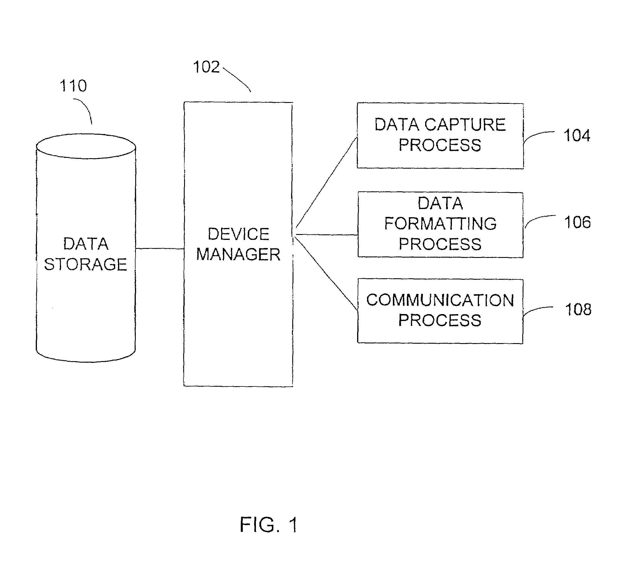
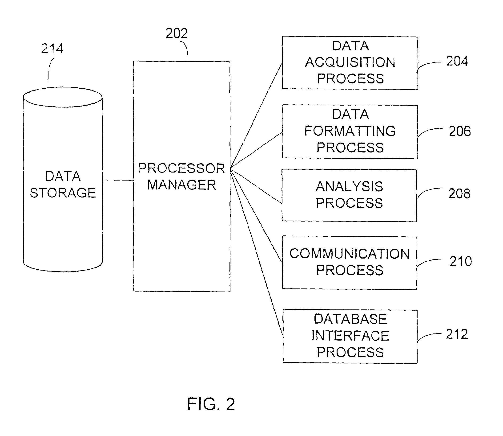
[0025]FIGS. 1 and 2 are simplified diagrams of modules 100 in a system for detecting and transmitting analyte data according to an exemplary embodiment of the present invention. These diagrams are merely an example which should not limit the scope of the claims herein. One of ordinary skill in the art would recognize many other variations, modifications, and alternatives. The system preferably includes a device manager 102 and a processor manager 202.

[0026]As shown in FIG. 1, the modules 104–108 include a variety of processes, which couple to the device manager 102. The processes include a data capture process 104, a data formatting process 106 and an I / O process 108. Other processes can be included. The device manager 102 also couples to data storage device 110 and oversees the processes. These processes can be implemented in software, hardware, firmware, or any combination of these in any one of the hardware devices, which will be described below, as well as others.

[0027]The data ...


PUM

PropertyMeasurementUnit
transmissionaaaaaaaaaa
electrical responseaaaaaaaaaa
timeaaaaaaaaaa

Abstract

A system for capturing and transmitting analyte data pertaining to an unknown analyte. The system includes a device manager (102) and a processor manager (202). The device manager (102) is coupled to a number of module including a data capture module (104), a data formatting module (106) and a first input / output (I / O) module (108). The data capture module (104) is coupled to the device manager (102) for capturing the data for the unknown analyte at a first geographic location. The first data formatting module (106) is coupled to the device manager (102) for formatting or encoding the captured analyte data into a transmissible format before the captured analyte data are transmitted. The first I / O module (106) is coupled to the device manager for transmitting the captured analyte data via a computer network to a processor at a second geographic location. The processor manager (202) is also coupled to a number of modules including a data acquisition process (204), a second data formatting module (206), an analysis module (208), a second I / O module (210) and a database interface module (210). The data acquisition module (204) is coupled to the processor manager (202) for receiving encoded analyte data from the device manager (102). The second data formatting module (206) is coupled to the processor manager (202) for decoding the encoded analyte data received by the data acquisition module (204) so as to permit analysis to be performed. The database interface module (212) is coupled to the processor manager (202) for retrieving data of known analytes from an electronic library before the decoded captured analyte data are analyzed. In addition, the database interface module (212) can be used for updating the electronic library with the decoded captured analyte data. The analysis module (208) is coupled to the processor manager (202) for performing analysis on the decoded captured analyte data using data from the electronic library and generating an analysis result. The second I / O module (210) is coupled to the processor manager (202) for managing communications between the processor manager (202) and other entities such as the device manager (102) and the electronic library. Depending upon the embodiment, other modules can also exist.

Description

CROSS-REFERENCES TO RELATED APPLICATIONS[0001]This application claims the benefit of priority from U.S. Provisional Patent Application Ser. No. 60 / 164,022, filed on Nov. 4, 1999, U.S. Provisional Patent Application Ser. No. 60 / 162,683, filed on Nov. 1, 1999, and U.S. Provisional Patent Application Ser. No. 60 / 188,312, filed on Mar. 10, 2000, all of which are hereby incorporated by reference as if set forth in full in this document.FIELD OF THE INVENTION[0002]This invention generally relates to the detection and transmission of sensory data. More particularly, the present invention relates to a system for detecting and transmitting sensory data from one portable device to another for analytic purposes.BACKGROUND OF THE INVENTION[0003]Techniques and devices for detecting a wide variety of analytes in fluids such as vapors, gases and liquids are well known. Such devices generally comprise an array of sensors that in the presence of an analyte produce a unique output signature. Using pa...

Claims


Application Information

Patent Timeline
Patent Type & Authority Patents(United States)
IPC IPC(8): G01N31/00G06F19/00
CPCG06F19/3418G06F19/3406G06F19/345G16H40/63G16H50/20G16H40/67
Inventor SUNSHINE, STEVEN A.
Owner SMITHS DETECTION
Learn More