Process and apparatus for treating biogenic residues, particularly sludges

a biogenic residue and processing equipment technology, applied in lighting and heating equipment, combustion process, drying, etc., can solve the problems of sludge disposal, difficult use, and limited disposal of waste, and achieve the effect of decentralizing the treatment of biogenic residues

Inactive Publication Date: 2005-12-27
KALOGEO ANLAGENBAU
View PDF11 Cites 21 Cited by
  • Summary
  • Abstract
  • Description
  • Claims
  • Application Information

AI Technical Summary

Benefits of technology

[0007]The object of the invention is thus to provide a process which avoids known drawbacks and makes sure a decentralized treatment of biogenic residues, particularly sludges with full conversion of the energy content stored in the sludge charged.

Problems solved by technology

The sometimes high fraction of biogenic residues in the sludges makes it quite difficult to use them again.
Disposal itself on dumps and in agriculture is limited in terms of volume the usage thereof is prevented especially because of pollutants in the sludge as well as the trend to biological farming.
Therefore, the moisture first removed from the process is added back which makes the overall process absurd from the standpoint of the energy balance.
Transporting the sludges to central plants generally entails high costs.
One major drawback in particular of the known processes for drying the sludge followed by thermal treatment is particularly the fact that exhaust air generated in the drying process is conducted to the incinerator because of increased fractions of pollutants.
Moreover, these processes also have the problem of odors and thus are not a solution either.
Even when a large amount of water is removed, processes providing only for drying the input material do not yield material that can be recycled or dumped.
Finally, known methods for treating sludges at temperatures up to approximately 600° C. do not provide a solution because they do not ensure complete conversion of hazardous materials such as residue from pharmaceuticals.

Method used


Image

  • Process and apparatus for treating biogenic residues, particularly sludges
  • Process and apparatus for treating biogenic residues, particularly sludges
  • Process and apparatus for treating biogenic residues, particularly sludges

Examples


Embodiment Construction

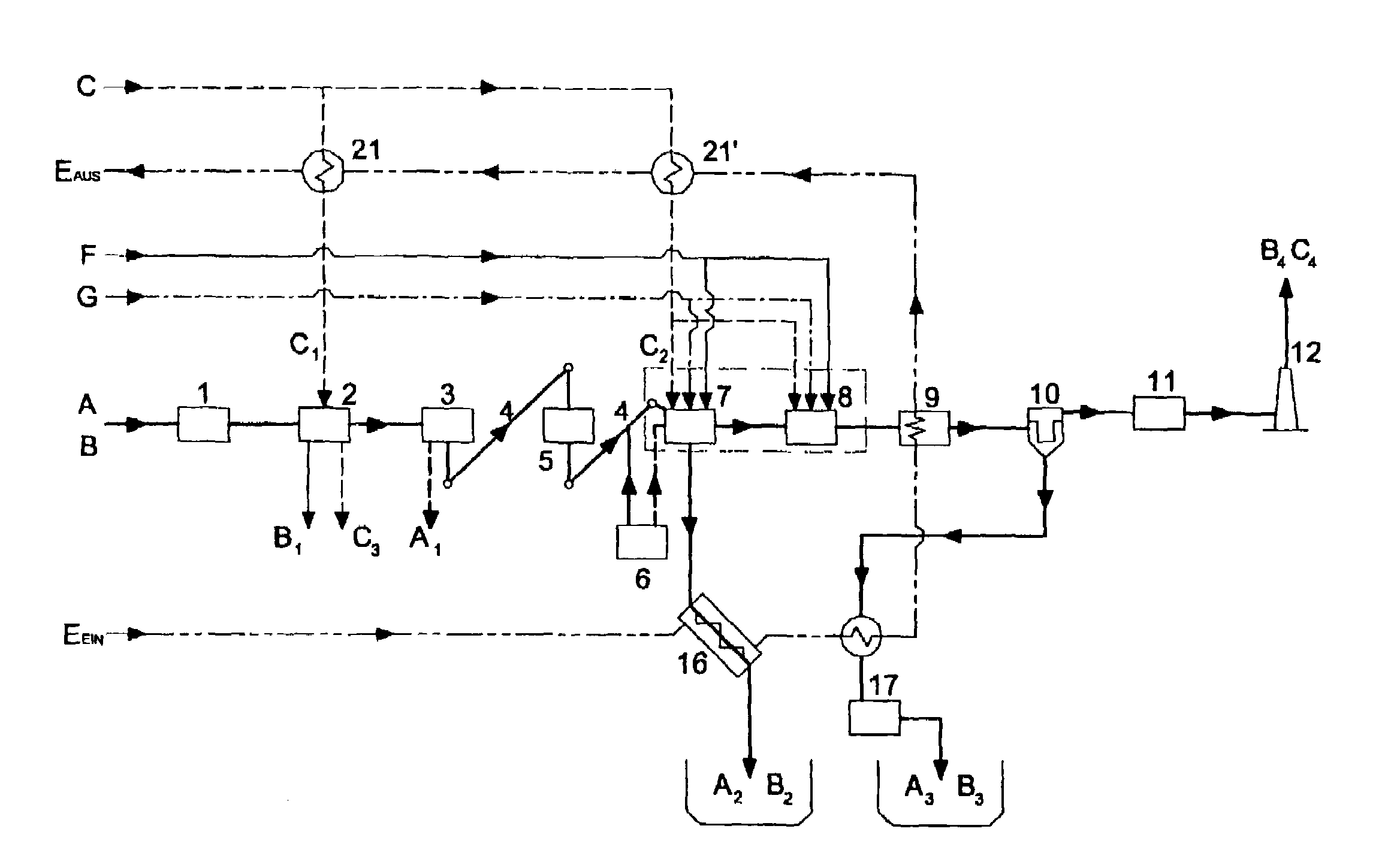
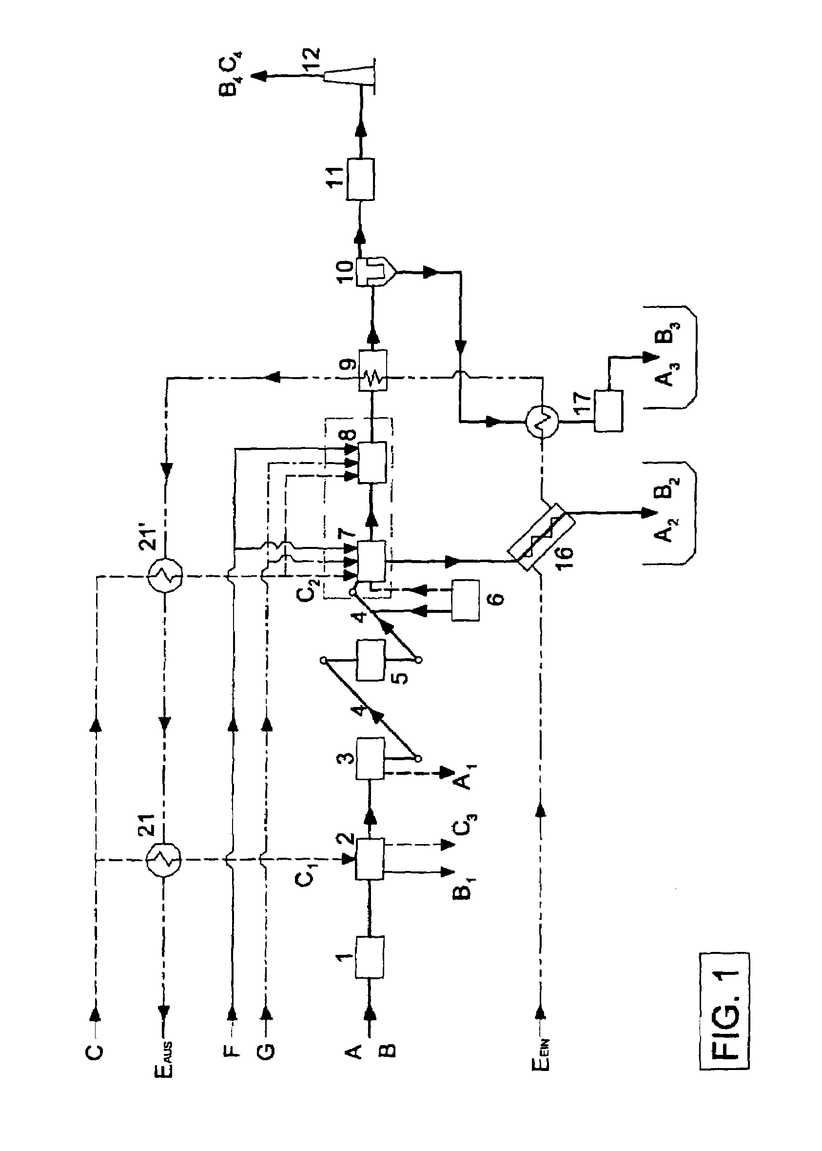
[0060]Referring now specifically to the drawings, wet sludge consisting of dry sludge A and supplied water B is fed to the wet sludge storage container 1 and stored intermediately there. In general, the wet sludge storage container can accommodate sludges having any consistency. Provision is also made for mixing of sludges with different consistencies.

[0061]The sludge is fed from the wet sludge storage container 1 to the drying unit. Drying is carried out by means of a low temperature drying system 2 which dries the sludge slowly in an environment of a maximum of 60 to 70° C. under aerobic conditions. The drying system 2 is modular in design. It is possible to increase the drying capacity and to make an adaptation for wet sludge with a higher water content. The air needed for drying is preheated by the waste heat of the thermal treatment system 7, 8 and fed to the drying system. Water B1 from the stream of wet sludge supplied is discharged from the low temperature drying system 2. T...


PUM


Abstract

The invention relates to a process and apparatus for treating biogenic residues, particularly sludges, preferably in the area of a clarification plant. Biogenic residues with a variable dry substance are subjected to aerobic drying until an energy-independent thermal treatment can be carried out. During the drying process, evaporated water is discharged in an odor-free condition without releasing freely volatile components, the dried sludge is intermediately stored a number of times and then utilized in preferably a number of successive thermal treatment steps. The two-stage cleaning of the stream of waste gas includes a dust collection unit and an adsorption unit. The waste heat is recycled through a heat exchanger to generate heat and electricity. The apparatus for carrying out the process includes a wet sludge storage container (1), a low temperature drying system (2), storage containers (3, 5) for intermediate storage of the dried biogenic residues, and a thermal treatment system with one or more thermal treatment steps (7, 8). Cleaning of the flue gas takes place preferably by means of a primary cleaning step (10) and a secondary cleaning step (11) for adsorption, for example, with clarified water. Energy recovery (9) from the hot waste gas is ideally carried out before the flue gas cleaning.

Description

TECHNICAL FIELD AND BACKGROUND OF THE INVENTION[0001]The invention relates to a process for treating biogenic residues, particularly sludges, preferably in the area of a clarification plant, as well as an apparatus for carrying out the process with arrangements for drying and incinerating the biogenic residues. Sludges from municipal sewage clarification or industrial plants are subjected at central plants to industrial conditioning for reutilization or conversion into product gas, for example. The sometimes high fraction of biogenic residues in the sludges makes it quite difficult to use them again. Substitution materials added for stabilization generally just increases the volumes of waste for disposal. Disposal itself on dumps and in agriculture is limited in terms of volume the usage thereof is prevented especially because of pollutants in the sludge as well as the trend to biological farming.[0002]In the known processes, drying of the material is generally carried out at high t...

Claims


Application Information

Patent Timeline
Patent Type & Authority Patents(United States)
IPC IPC(8): F23G5/00F23G5/02F23G5/46F23G7/00F23J15/00F26B3/34F26B23/00F26B25/00
CPCF23G5/006F23G5/02F23G5/46F23G7/001F23J15/006F26B23/002F26B23/007F26B25/005F23G2201/10F23G2206/10F23G2206/20F26B2200/18Y02E20/12Y02P70/10
Inventor RAMHARTER, PETER MICHAELBAYER, HARALD
Owner KALOGEO ANLAGENBAU
Why Eureka
Try Eureka