Method and apparatus to control a variable valve control device

a control device and variable valve technology, applied in the direction of valve details, non-mechanical valves, valve arrangements, etc., can solve the problems of reducing the range of motion of the valve, affecting the volumetric efficiency of the internal combustion engine, and the controller's inability to precisely control the variable valve control system. , to achieve the effect of reducing the energy consumption of the oil pump and improving the response time of the variable valve timing devi

Inactive Publication Date: 2005-12-27
DELPHI TECH INC
View PDF25 Cites 12 Cited by
  • Summary
  • Abstract
  • Description
  • Claims
  • Application Information

AI Technical Summary

Benefits of technology

[0010]The present invention provides an improvement over conventional engine control systems with variable valve timing devices for the valvetrain in that it provides a closed-circuit hydrostatic fluid control system to improve response time of the variable valve timing device and reduce energy consumption by the oil pump. The hydrostatic fluid control system preferably comprises a bi-directional fluid-pumping device that is fluidly connected to the variable valve control device. A controller is operable to control the bi-directional fluid-pumping device and operable to determine rotational position of the variable valve control device. Hence, the controller controls the bi-directional fluid pumping device based upon the rotational position of the variable valve control device, relative to crankshaft position. The bi-directional fluid-pumping device comprises a substantially positive-displacement pump element that is operably attached to an electric motor electrically operably connected to the controller. The variable valve control device comprises a variable cam phaser operably attached to a camshaft. In the alternative, the variable valve control device can comprise a variable valve timing device, or a variable valve lift and duration device. The invention also includes a fluid pumping device that has unidirectional flow, and employs flow switching valves to accomplish change in flow direction to the variable valve timing device.

Problems solved by technology

Timing, duration, and amplitude of valve opening affects mass of air that flows into an individual cylinder, thus affecting volumetric efficiency of the internal combustion engine.
These system factors include, for example, oil contamination, wear and viscosity, part-to-part variability caused by manufacturing tolerances, engine operating temperature, and component wear.
These factors result in an inability of the controller to precisely control the variable valve control system, including a reduction in the range of motion of the valve.
Any benefits derived from the variable valve control system can be compromised as a result.
It is apparent that a portion of oil pumping capacity is unused over much of the life of the engine.
This extra capacity adds unnecessary cost to the pump and consumes energy during operation.

Method used


Image

  • Method and apparatus to control a variable valve control device
  • Method and apparatus to control a variable valve control device
  • Method and apparatus to control a variable valve control device

Examples


Embodiment Construction

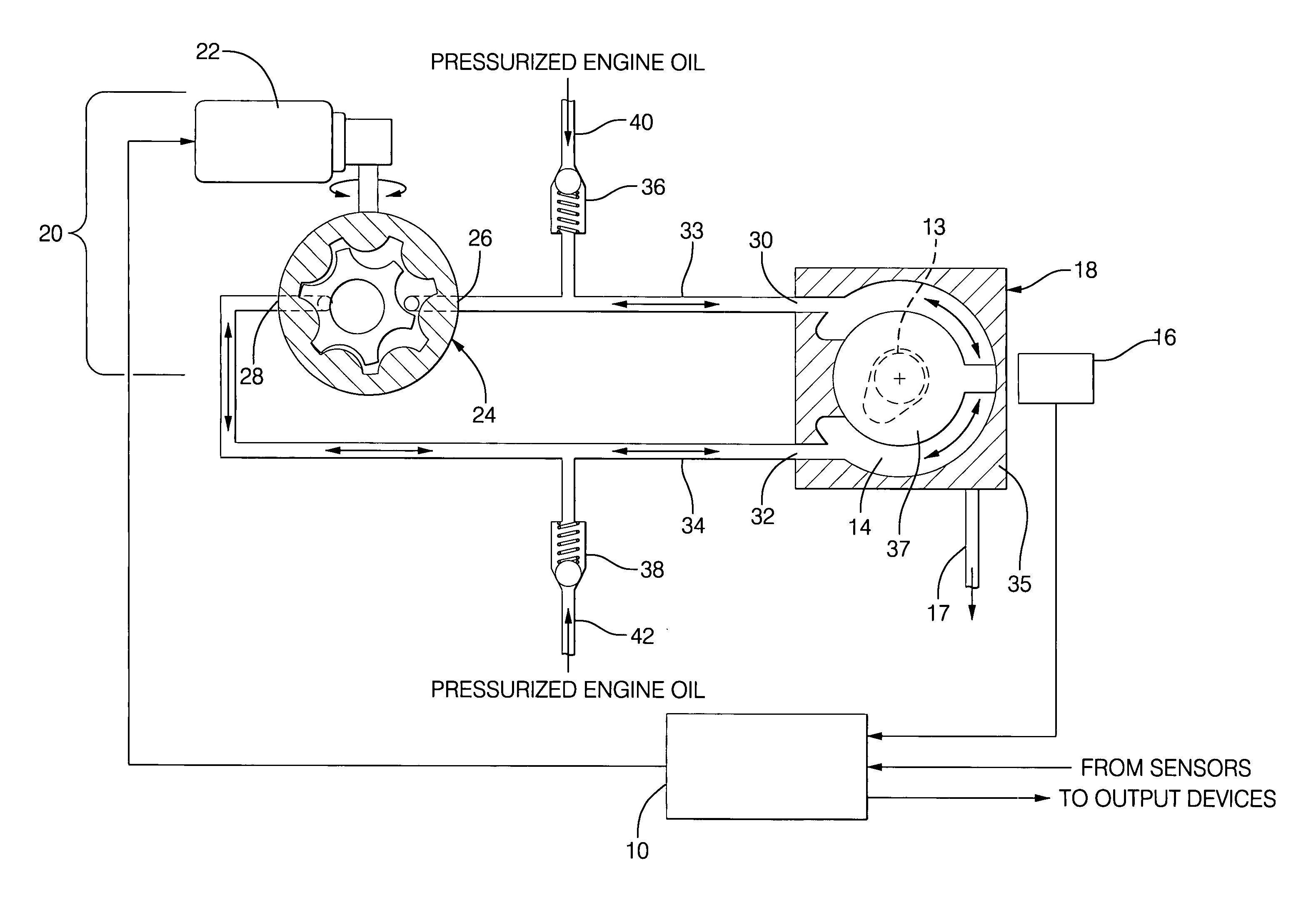
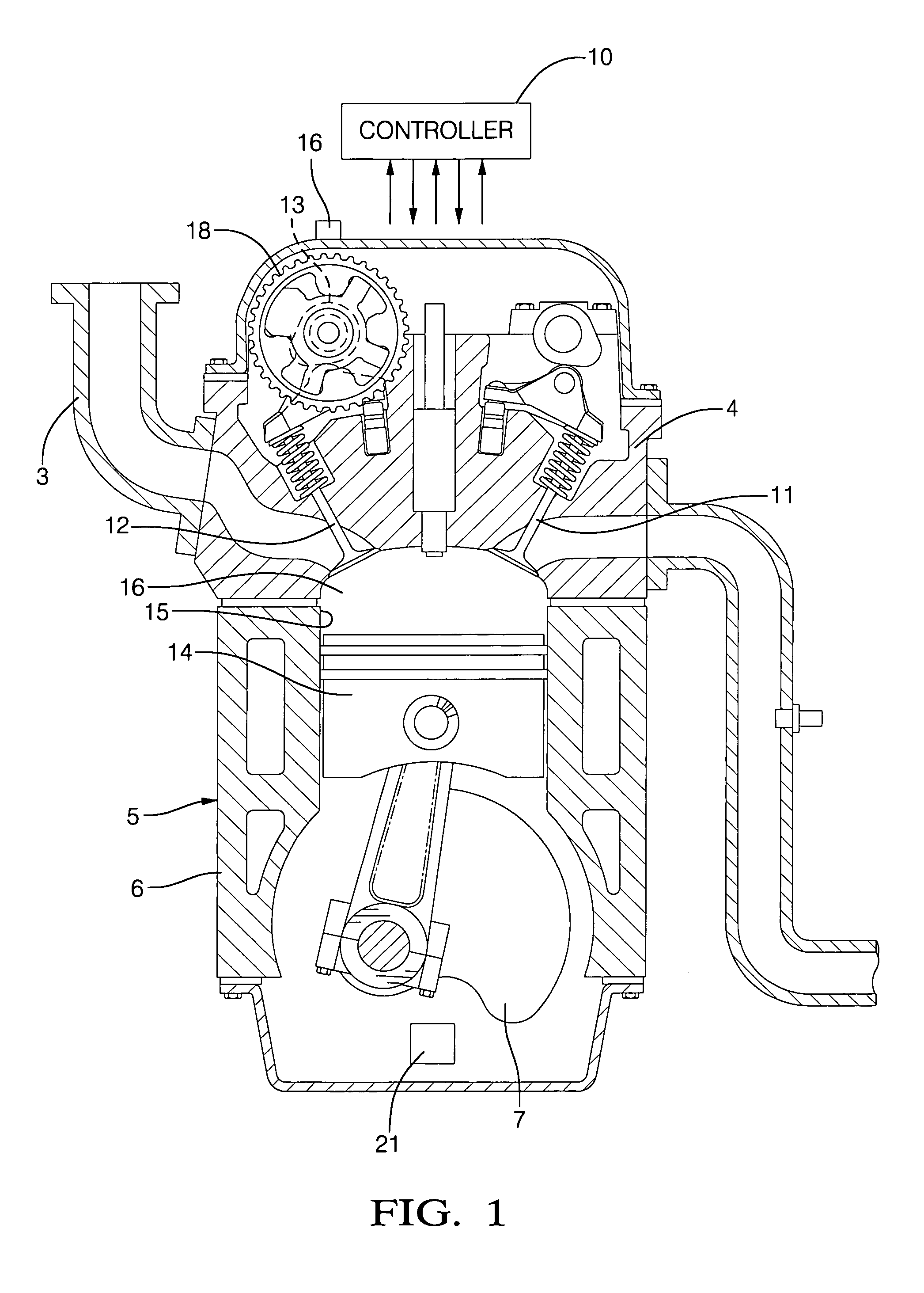
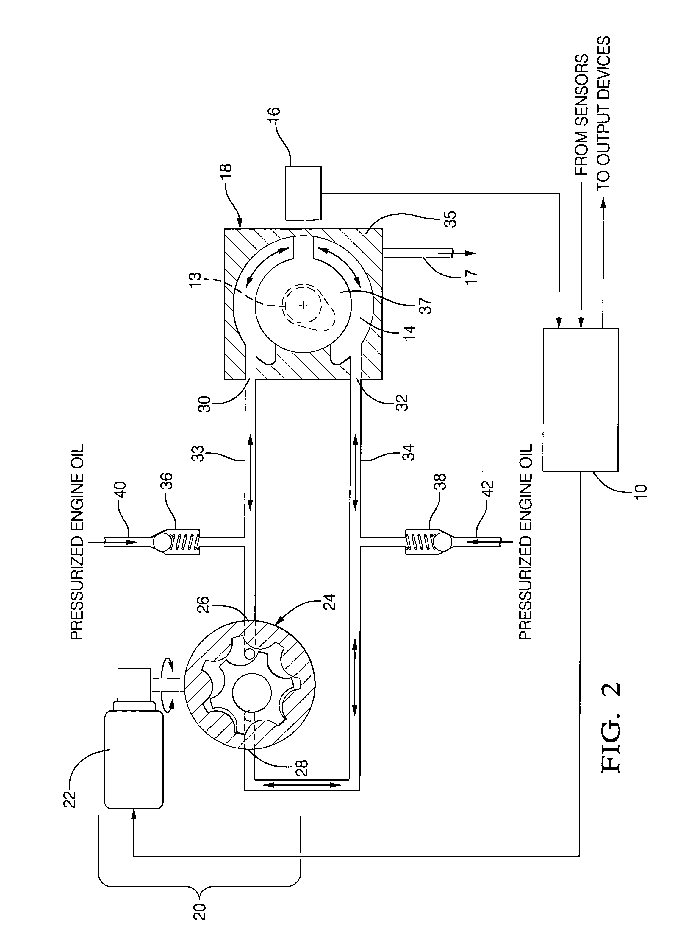
[0017]Referring now to the drawings, wherein the showings are for the purpose of illustrating an embodiment of the invention only and not for the purpose of limiting the same, FIG. 1 shows an internal combustion engine 5, controller 10 and substantially closed-circuit hydrostatic fluid control system for controlling a variable valve control device 18 which has been constructed in accordance with an embodiment of the present invention. In this embodiment, the variable valve control device 18 comprises a variable cam phaser 18 operably attached to an intake camshaft 13. The substantially closed-circuit hydrostatic fluid control system comprises a bi-directional fluid-pumping device (See FIG. 2, item 20) fluidly connected to the variable cam phaser 18. The controller 10 is operable to control the bi-directional fluid-pumping device 20 and to determine a position of the variable cam phaser 18, using a cam position sensor (See FIG. 2, item 16). The controller 10 controls the bi-direction...


PUM


Abstract

The present invention provides an improvement over conventional engine control systems for variable valve control devices for the valvetrain in that it provides a substantially closed-circuit hydrostatic fluid control system and accompanying method to improve response time of the variable valve control device and reduce energy consumption by an engine oil pump. The hydrostatic fluid control system preferably comprises a bi-directional fluid-pumping device that is fluidly connected to a variable valve control device. A controller is operable to control the bi-directional fluid-pumping device and operable to determine rotational position of the variable valve control device.

Description

TECHNICAL FIELD[0001]This invention pertains generally to internal combustion engine control systems, and more specifically to a method and apparatus to operate a variable valve control device using a hydrostatic fluid control system.BACKGROUND OF THE INVENTION[0002]Engine manufacturers incorporate valve train systems with variable valve control systems to improve operating and emissions performance of internal combustion engines. These variable valve control systems include systems to accomplish variable cam phasing, cylinder deactivation, and variable valve lift and duration. Distinct engine operating characteristics resulting from use of the variable valve system include improved combustion stability at idle, improved airflow through the engine over a range of engine operations corresponding to improvements in engine performance, and improved dilution tolerance in a combustion charge. Benefits of incorporating the variable valve system into an engine include improved fuel economy...

Claims


Application Information

Patent Timeline
Patent Type & Authority Patents(United States)
IPC IPC(8): F01L1/34F01L1/344F01L13/00
CPCF01L1/34F01L1/3442F01L13/0015F01L1/024F01L2201/00
Inventor KIBLER, ROLAND GLENN
Owner DELPHI TECH INC
Why Eureka
Try Eureka