Soft switching interleaved power converter

a power converter and interleave technology, applied in the direction of power conversion systems, dc-dc conversion, instruments, etc., can solve the problems of prohibitively high switching losses, limited prior art power supplies that utilize hard-switching power converters operating frequencies, and reduce the energy that can be supplied to plasma arcs, etc., to achieve diode reverse recovery losses and reduce switching losses

Active Publication Date: 2005-12-27
AES GLOBAL HLDG PTE LTD
View PDF11 Cites 69 Cited by
  • Summary
  • Abstract
  • Description
  • Claims
  • Application Information

AI Technical Summary

Benefits of technology

[0024]There is provided by this invention soft switching interleaved power converters that are suitable for high power and high voltage applications such as plasma processing. They can operate at higher frequencies than prior art converters because they have greatly reduced switching losses and diode reverse-recovery losses. The peak values of the reverse-recovery currents of the diodes are substantially less than their peak forward oper

Problems solved by technology

High-frequency operation allows the use of smaller output filter capacitors, which store less energy than larger capacitors, and this reduces the energy that can be supplied to plasma arcs.
The operating frequencies prior art power supplies that utilize hard-switching power converters are limited because the switching losses can become prohibitively high as the operating frequency is increased.
This produces switching losses that may be prohibitively high in hard switching power converters that operate at high voltage and power levels while switching at high frequencies.
In general, high voltage diodes turn off more slowly than low voltage diodes, so switching losses are a particular problem for high-frequency power converters that operate at high voltages and high power levels.
When hard-switched power converters are used in high-voltage and high-power applications as disclosed in U.S. Pat. No. 6,211,657, the switching losses will be considerable when the power converter is operated at high switching frequencies.
The large revers

Method used


Image

  • Soft switching interleaved power converter
  • Soft switching interleaved power converter
  • Soft switching interleaved power converter

Examples


Embodiment Construction

[0041]The power converter cells of the present invention are similar in structure to prior art circuits, but they achieve heretofore unknown performance improvements by utilizing inductor assemblies with advantageous structures and inductance values, and by utilizing optimal switching patterns.

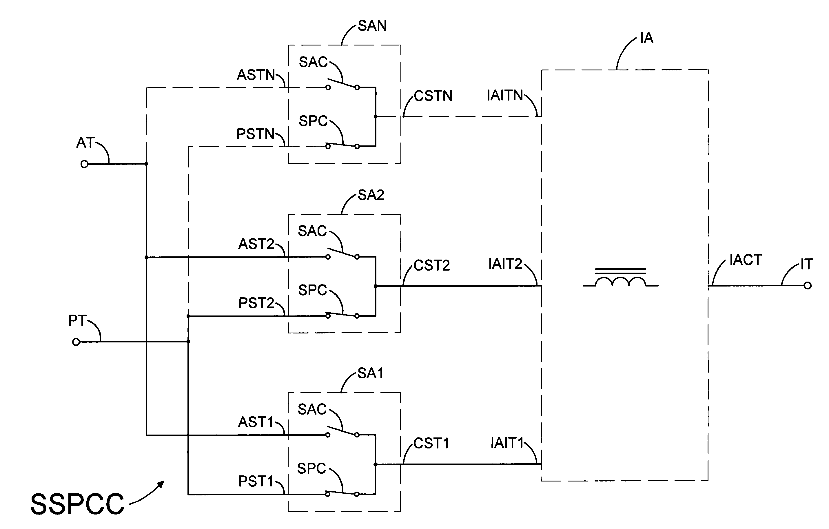
[0042]FIG. 12 illustrates a soft switching power converter cell SSPCC according to the present invention. At least two switching assemblies, SA1 and SA2, are connected to active and passive terminals, AT and PT. The possibility of connecting more switching assemblies, for a total of N is indicated by the dashed connections to the Nth switching assembly SAN. The common terminal of each switch assembly, CST1 . . . CSTN is connected to an inductor assembly, IA, at an inductive assembly input terminal, IAIT1 . . . IAITN. An inductor assembly common terminal IACT is connected to the inductive terminal IT of the SSPCC power converter cell.

[0043]FIGS. 13–16 show various ways to implement inductor ass...


PUM


Abstract

There is provided by this invention soft switching interleaved power converters that are suitable for high power and high voltage applications such as plasma processing. They have greatly reduced switching losses and diode reverse-recovery losses which allows operation at high switching frequencies. The peak values of the reverse-recovery currents of the diodes are substantially less then their peak forward operating currents. The power converters incorporate power converter cells that comprise a plurality of switching assemblies that are operated with an interleaved switching pattern, and that are each connected to an input terminal of an inductor assembly that also has a common terminal. The inductance between each pair of input terminals is less than the inductance between each input terminal and the common terminal of the inductor assembly.

Description

BACKGROUND OF THE INVENTION[0001]1. Field of the Invention[0002]This invention relates generally to soft switching switch mode power converters, and more particularly, to soft switching buck, buck-boost and boost switch mode power converters suitable for high power and high voltage applications such as plasma processing.[0003]2. Brief Description of the Prior Art[0004]It is generally desirable to operate switching power supplies at the highest frequency that is practical for a particular circuit. Operating at higher frequencies allows the inductor and capacitor values in a power supply to be reduced, and this reduces physical size and cost, and also enables improvements in the transient response of the power supply. Reducing the energy available for delivery to plasma arcs is also a desirable goal. High-frequency operation allows the use of smaller output filter capacitors, which store less energy than larger capacitors, and this reduces the energy that can be supplied to plasma arc...

Claims


Application Information

Patent Timeline
IPC IPC(8): G05F1/613G05F1/656H02M3/07H02M3/158
CPCH02M3/07H02M3/1584H02M2003/075H02M2003/076H02M2003/1586H02M3/075H02M3/076H02M3/1586G05F1/652
Inventor HESTERMAN, BRYCE L.ILIC, MILANMALININ, ANDREY B.SIDDABATTULA, KALYAN N. C.
Owner AES GLOBAL HLDG PTE LTD
Why Eureka
Try Eureka